Water saver toilet with uniform water spot

a water spot and toilet technology, applied in water installations, flushing devices, constructions, etc., can solve the problem of less water available to create a water spot, and achieve the effect of providing a water spot in the toilet bowl and uniform water spot siz

Active Publication Date: 2012-03-27
P & C HENNESSY HLDG
View PDF2 Cites 9 Cited by
  • Summary
  • Abstract
  • Description
  • Claims
  • Application Information

AI Technical Summary

Problems solved by technology

However, when less water is flushed, less water may be available to create a water spot.

Method used


Image

  • Water saver toilet with uniform water spot
  • Water saver toilet with uniform water spot
  • Water saver toilet with uniform water spot

Examples


Embodiment Construction

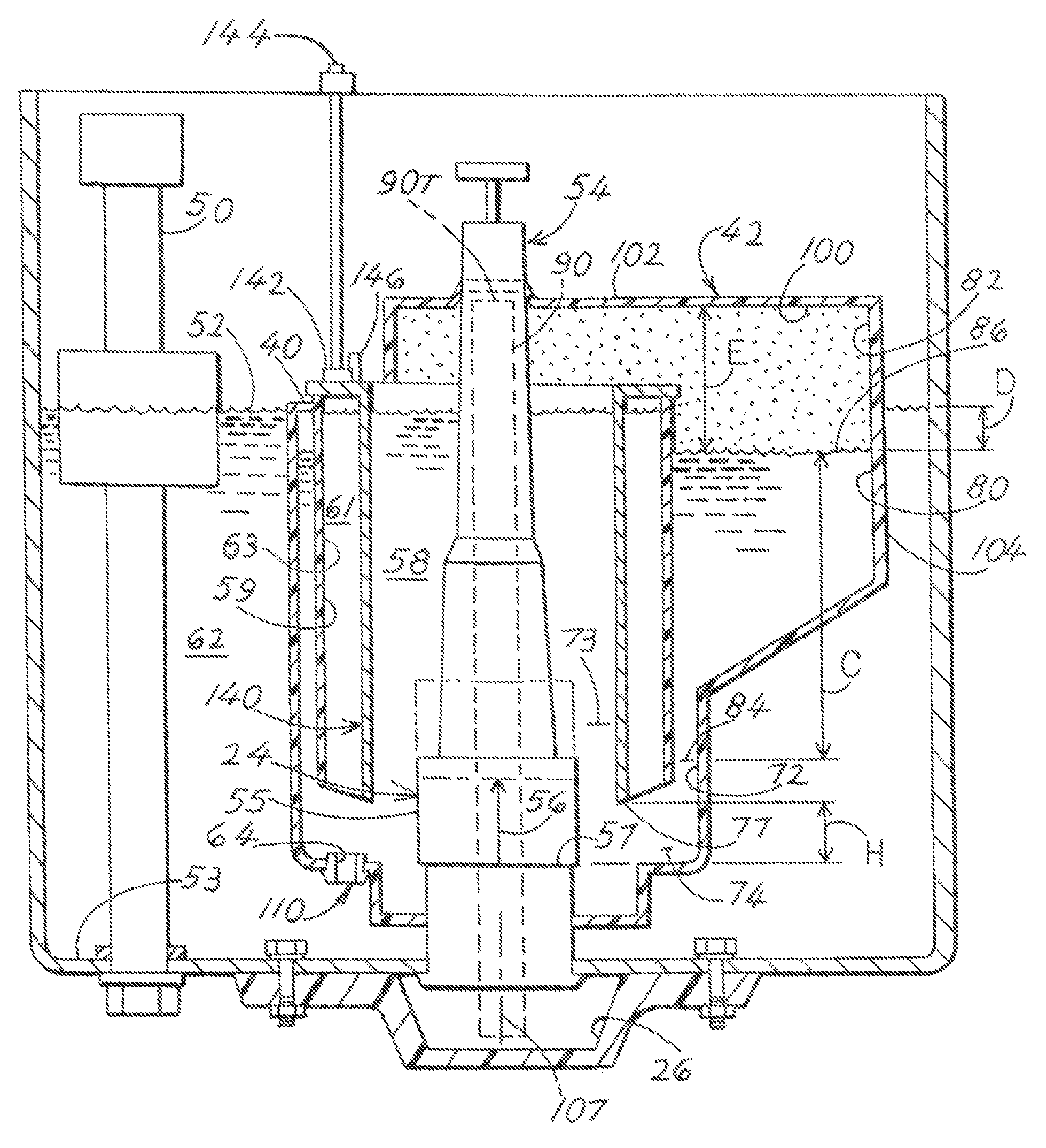
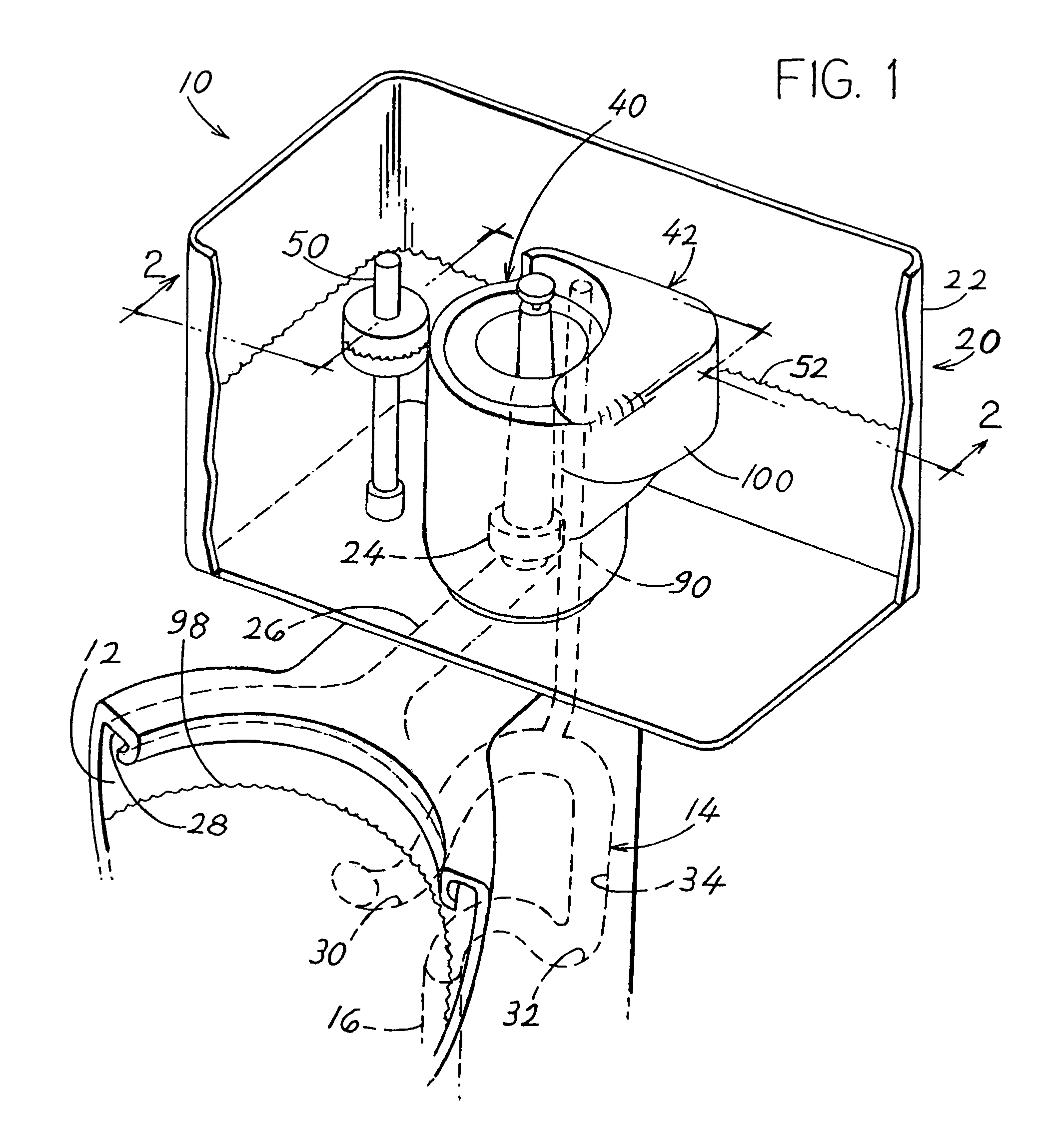
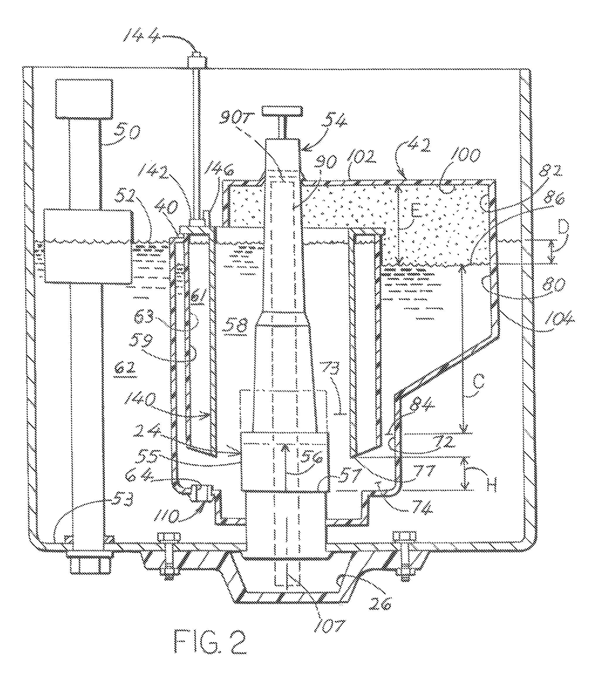
[0009]FIG. 1 shows a toilet 10 of the present invention, which includes a pottery section comprising a toilet bowl 12 that contains a water spot 98. A trapway 14 leads from the toilet bowl to a drain 16. A water supply 20 includes a water tank 22. A flush valve 24 in the water tank rapidly discharges water that has been stored within an isolator 40 that lies in the tank. During a flushing, discharged water flows through the water tunnel 26, through a channel 28 at the top of the toilet bowl, and through openings in the channel into the toilet bowl. The trapway includes upper and lower traps 30, 32 and a trapway passage 34 that extends between them. The water supply 20 includes the isolator 40 and an air-water source 42 that both lie in the tank 22, and that are part of a single structure. A refill valve 50 slowly admits water into the tank after each flushing, until the water level in the tank reaches a tank filled level 52. The flush valve 24 lies in the bottom of the isolator 40 w...


PUM


Abstract

A toilet has a source (42) that applies a vacuum to a trapway (14) at the beginning of a flushing to immediately flush the toilet bowl (12). As a result, water from the water tunnel 26 and the toilet bowl top channel 28 flow into the bowl after the flushing to create a large water spot (98) in the toilet bowl. A low water flush (e.g. 1½ liters to flush urine) can be obtained by not letting water flow out of a secondary volume (63) that lies outside a divider (140) in an isolator (40).

Description

BACKGROUND OF THE INVENTION[0001]Conventional toilets create a water spot in the toilet bowl at the end of each flushing, by using a refill valve that dispenses some water to the toilet bowl. In a water saver toilet, care must be taken in its design to assure a water spot of sufficient size.[0002]It is possible to save water when flushing only urine by using perhaps 1.5 liters instead of 3 liters in a water saver toilet flushing. However, when less water is flushed, less water may be available to create a water spot. A toilet that enabled a good flushing with only about 1.5 liters of water, and that provided a sufficiently large toilet bowl spot would be of value.SUMMARY OF THE INVENTION[0003]In accordance with one embodiment of the present invention, a water saver toilet is provided that includes a water source which reliably provides a water spot in the toilet bowl. A full flush (e.g. 3 liters) or a low water flush (e.g. 1½ liters) can be selected. In either case, the toilet bowl ...

Claims


Application Information

Patent Timeline
Patent Type & Authority Patents(United States)
IPC IPC(8): E03D1/06
CPCE03D1/142E03D2201/30Y02A20/40
Inventor HENNESSY, PHILIP
Owner P & C HENNESSY HLDG
Why Eureka
Try Eureka