Thermal bypass valve with pressure relief capability

a bypass valve and heat exchanger technology, applied in the direction of machines/engines, process and machine control, instruments, etc., can solve the problems of high pressure, damage or erratic performance, and cumulative damage to the transmission, so as to reduce the excessive pressure and extend or retract in dependence

Active Publication Date: 2012-03-27
DANA CANADA CORP
View PDF15 Cites 35 Cited by
  • Summary
  • Abstract
  • Description
  • Claims
  • Application Information

AI Technical Summary

Benefits of technology

[0007]According to one exemplary embodiment of the present disclosure, a by-pass valve apparatus for a heat exchanger circuit for cooling a heat exchange fluid comprises a by-pass valve device having a valve housing formed with a valve chamber with opposite first and second end sections, a first port for inflow of the heat exchange fluid into the second end section, a second port for outflow of the heat exchange fluid from the second end section to a cooler, a third port for outflow of the heat exchange fluid from the first end section, and a fourth port for the inflow of the heat exchange fluid into the first end section from the cooler. A thermally sensitive actuator is mounted in the chamber and is adapted to extend or retract in dependence on its temperature which is influenced by the temperature of the heat exchange fluid during use of the valve apparatus. The actuator has a first end disposed in the second end section and a second end disposed towards the first end section. A by-pass valve seat is provided in the valve housing and a by-pass valve member is mounted in the valve chamber and movable by extension or retraction of the actuator into engagement with or disengagement from the valve seat in order to open or close a by-pass port for flow of the heat exchange fluid from the second end section to the first end section. There is also a relief valve mechanism mounted in the valve chamber and having at least one relief valve member movable between a closed position where at least one pressure relief port is closed and an open position where said at least one pressure relief port is open. The at least one relief valve member is biased towards the closed position. In event of excessive pressure build up in the second end section of the chamber during use of the by-pass valve, the pressure of the heat exchange fluid in the second end section causes the at least one relief valve member to move to its open position and thereby reduce the excessive pressure.
[0009]In another exemplary embodiment of a by-pass valve according to the present disclosure, the by-pass valve for a heat exchanger circuit for cooling a heat exchange fluid includes a valve housing formed with a valve chamber and having first and second ports for respectively supplying and returning the heat exchange fluid to and from the chamber and third and fourth ports for respectively supplying and returning the heat exchange fluid to and from a cooler. The valve also has a thermally sensitive actuator mounted in the chamber and having a shaft section and a piston extending from a first end of the actuator. The piston is adapted to extend from or retract into the first end in dependence on the temperature of the shaft section, this piston extending into and held by a recess formed in the housing at one end of the chamber so that the shaft section is movable in the chamber and responds to extension or retraction of the piston. A spring enclosure is mounted in a by-pass section of the chamber adjacent a second end of the actuator remote from the first end. This spring enclosure forms a valve seat having a by-pass port through which the heat exchange fluid can flow in a cold by-pass state of the valve and forming at least one pressure relief port. There is at least one port closing device mounted in or on the enclosure and adapted under normal operating conditions to close the at least one pressure relief port. A by-pass valve member is mounted on the shaft section and is movable by the actuator from a first position where the by-pass port is open to a second position where the by-pass port is closed by the by-pass valve member. A return spring is mounted in the enclosure and has one spring end engaging the actuator at the second end thereof so as to bias the shaft section away from the valve seat and the by-pass port. In the event of excessive pressure build-up in the chamber on the actuator side of the valve seat during use of the by-pass valve, the at least one port closing device moves to an open position and allows the heat exchange fluid to flow through the at least one pressure relief port and thereby reduce the pressure build-up.
[0011]According to another example embodiment of a by-pass valve according to the present disclosure, a by-pass valve for mounting between a transmission and a cooling unit used to cool a transmission fluid for the transmission includes a valve housing having a valve chamber, first aperture means connected to the valve chamber for supplying and returning the transmission fluid to and from the transmission and second aperture means connected to the valve chamber for supplying and returning the transmission fluid to and from the cooling unit. The valve has a thermally sensitive actuator mounted in the chamber and having an actuator body with opposite first and second ends and a piston extending from the first end. The piston is adapted to extend from the first end or retract into the body in dependence on the temperature of the body. The piston is adapted and arranged to engage the housing at one end of the valve chamber so that the body is linearly movable in the chamber in response to extension or retraction of the piston. A valve seat member is provided in the valve chamber adjacent the second end of the actuator, this seat member forming a by-pass opening through which the transmission fluid can flow in a first direction in a cold by-pass state of the valve. This seat member also forms a pressure relief port arrangement through which the transmission fluid can flow in a reverse direction opposite the first direction. A relief valve mechanism is mounted in the valve chamber and is movable between a closed position where the pressure relief port arrangement is closed and an open position where the pressure relief port arrangement is open. This relief valve mechanism is biased towards the closed position. There is also a by-pass valve member mounted in the valve chamber and movable by the actuator body from a by-pass position where the by-pass opening is open to a valve seat engaging position where the by-pass opening is closed. A return spring is provided to bias the actuator to a piston retracted position. This spring has a first spring end engaging the second end of the actuator body and a second spring end engaging a supporting surface located within the chamber. In the event of excessive pressure build-up in a section of the chamber containing the actuator during use of the by-pass valve, the relief valve mechanism moves to its open position to allow the transmission fluid to flow through the pressure relief port arrangement and thereby reduce the pressure build-up.

Problems solved by technology

However, when the transmission is cool, such as at start up conditions, the transmission oil or fluid is very viscous and does not flow easily through the heat exchanger, if at all.
In such cases, the transmission can be starved of oil and this may cause damage or erratic performance.
Cumulative damage to the transmission can also occur if the quantity of oil returned is adequate but is over cooled due to low ambient temperatures.
In this case, for instance, moisture condensation in the oil (that would otherwise be vaporized at higher temperatures) may accumulate and cause corrosion or oil degradation.
A difficulty with this forward flow arrangement for a by-pass valve is that there is no provision for pressure relief in the event of excessive pressure build up in the one end section of the valve chamber that contains the actuator.

Method used


Image

  • Thermal bypass valve with pressure relief capability
  • Thermal bypass valve with pressure relief capability
  • Thermal bypass valve with pressure relief capability

Examples


Embodiment Construction

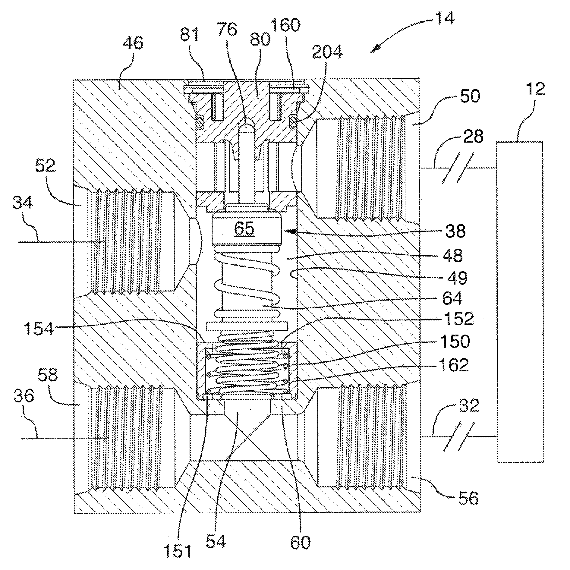
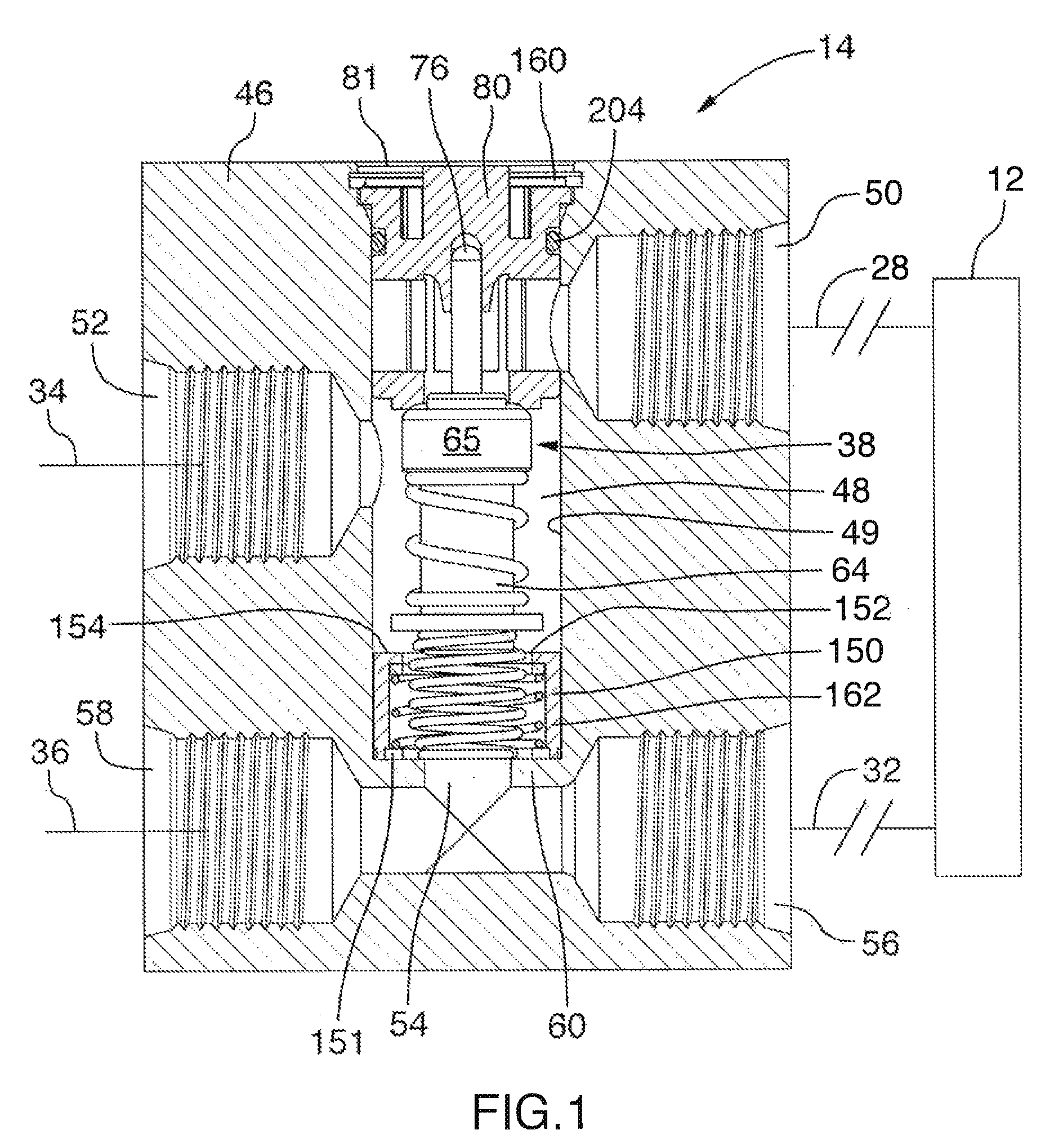
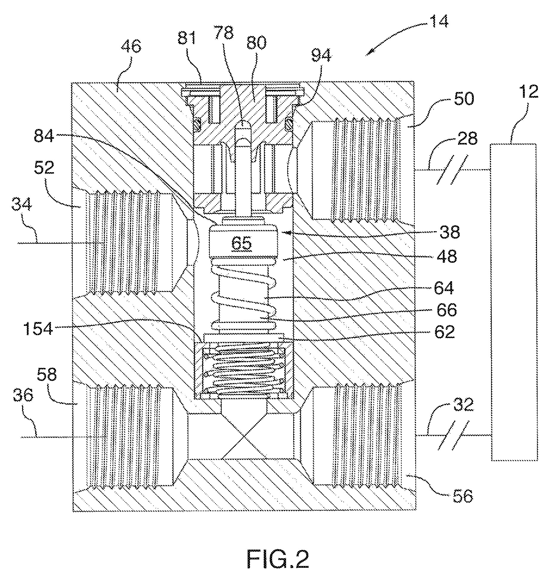
[0037]With reference to FIGS. 1 and 2, there is shown an example of a by-pass valve, indicated generally by reference 14, which can be used in a heat exchanger circuit to control the flow of a fluid, such as transmission fluid, to a heat exchanger 12 to which first and second conduits 28 and 32 are connected. The heat exchanger 12 can be a cooler or cooler unit of standard construction if it is being used to cool transmission fluid or transmission oil. The conduits 28, 32 are connected to an outlet port 50 and an inlet port 56 of the valve. These ports can also be considered aperture means which are connected to a valve chamber 48 for supplying and returning the transmission fluid to and from the heat exchanger 12. Conduits 34, 36 are also connected to ports 52, 58 in the valve 14 and these conduits 34, 36 can be connected to a vehicle component such as a transmission (not shown). The valve 14 is referred to as a four port by-pass valve because the four conduits 28, 32, 34 and 36 ar...


PUM


Abstract

A by-pass valve for a heat exchanger circuit that includes a cooler has a chamber and ports for flow of fluid into and out of this chamber. A thermally sensitive actuator is mounted in the chamber and can extend or retract in dependence on its body temperature as influenced by temperature of the fluid. A by-pass valve seat is arranged in a valve housing along with a by-pass valve member movable by the actuator into or out of engagement with the seat. A relief valve is mounted in the chamber and has a relief valve member movable between closed and open positions in order to close or open pressure relief ports. This relief valve member is biased towards the closed position. Excessive pressure build up in an end section of the chamber causes the relief valve member to move to its open position.

Description

BACKGROUND OF THE INVENTION[0001]This invention relates to by-pass valves for heat exchanger circuits in which there is a cooler or cooler unit for a heat exchange fluid.[0002]In the automotive industry, for example, heat exchangers are used to cool or heat certain fluids, such as engine oil or transmission fluid or oil. In the case of transmission fluid for instance, a heat exchanger, which can be called a cooler, is used to cool the transmission fluid. The heat exchanger is usually located remote from the transmission and, in normal operating conditions, it receives hot transmission oil from the transmission through supply tubing, cools it and delivers it back to the transmission through return tubing. However, when the transmission is cool, such as at start up conditions, the transmission oil or fluid is very viscous and does not flow easily through the heat exchanger, if at all. In such cases, the transmission can be starved of oil and this may cause damage or erratic performanc...

Claims


Application Information

Patent Timeline
Patent Type & Authority Patents(United States)
IPC IPC(8): F01P7/16
CPCF01P7/16F16K17/04F16K31/002G05D23/1333Y10T137/6579
Inventor SHEPPARD, JEFFREY OWEN
Owner DANA CANADA CORP
Why Eureka
Try Eureka