Computationally efficient demodulation for differential phase shift keying

a phase shift keying and differential phase shift technology, applied in the field of communication, can solve the problems of high computational cost of correlation and best sample selection process, high degree of computation in a short period consumes significant battery power, and continues to consume battery power at a high rate, so as to reduce or no dependence on complex mathematics, significant computational efficiency, and power consumption requirements

Inactive Publication Date: 2005-01-13
HONEYWELL INT INC
View PDF16 Cites 33 Cited by
  • Summary
  • Abstract
  • Description
  • Claims
  • Application Information

AI Technical Summary

Benefits of technology

[0017] Embodiments of the present invention perform DPSK demodulation with reduced or no dependence upon complex mathematics and without complex correlation of a known header. In addition, embodiments of the present invention provide for continuous frequency offset tracking and adjustment. Moreover, embodiments of the present invention perform significant demodulation tasks at the symbol rate rather than at the sample rate. Each of these features of the present invention, as well as others to be described subsequently, contribute to the significant computational efficiencies and corresponding reduction in power consumption requirements offered by embodiments of the present invention.

Problems solved by technology

The correlation and best sample selection processes are very expensive computationally because all computations must be completed with one sample interval.
This high degree of computation in a short period consumes significant battery power and continues to consume battery power at a high rate even after the correlation and best sample selection processes are completed.
Such complex mathematics is computationally expensive, and as a result consume significant amounts of power.
Moreover, once the correlation of the header samples is performed to determine frequency offset, conventional DPSK demodulators no longer check for frequency offset.
Often, this assumption is not valid, and communication quality degrades significantly.
Consequently, the ability to track phase and frequency offset errors, which are calculated only from the header correlation, is lost.
As a result, additional phase angle and frequency error acquisition and tracking circuitry is often required.
Such additional circuitry is also computationally very expensive and consequently, requires a great deal of power.

Method used


Image

  • Computationally efficient demodulation for differential phase shift keying
  • Computationally efficient demodulation for differential phase shift keying
  • Computationally efficient demodulation for differential phase shift keying

Examples


Embodiment Construction

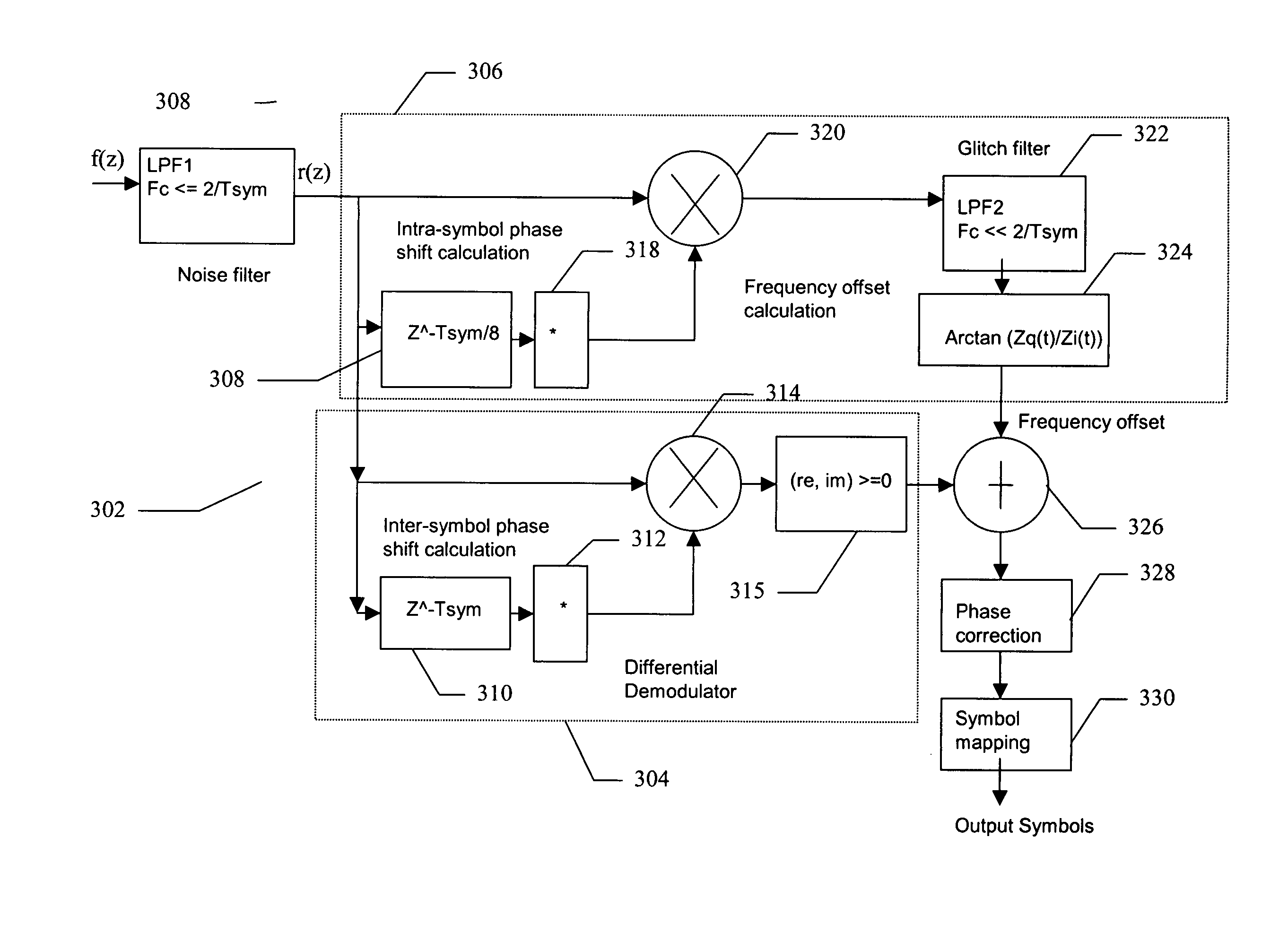
[0031]FIG. 3 is a schematic diagram of a computationally efficient M-ary DPSK demodulator 302 for demodulating a received DPSK signal according to an embodiment of the present invention. Demodulator 302 comprises two primary processing circuits. A differential demodulator circuit 304 demodulates the received signal to determine a phase associated with a received symbol. A frequency offset calculation circuit 306 determines any frequency offset associated with the received signal.

[0032] The demodulator of the present invention can be used in any DPSK communication application. Such communication applications include, for example, satellite, terrestrial and airborne communications. Further, as will be discussed in more detail subsequently, its low power consumption characteristics make it ideal for use in communication systems having low power consumption requirements.

[0033] In operation, DPSK signal is received in a receiver through an antenna. The input signal is sampled in an A / D...


PUM


Abstract

A DPSK demodulator demodulates DPSK signals in a computationally efficient manner to reduce the power requirements of the DPSK demodulator. A DPSK signal is received, digitized, converted to its in-phase (I) and quadrature (Q) components and filtered to remove noise. The I and Q components are processed to determine a relative phase and frequency offset. The phase is adjusted using the frequency offset. The adjusted phase is converted to an absolute phase, which is then mapped to a symbol representative of one or more bits of data.

Description

BACKGROUND [0001] 1. Field of the Invention [0002] Embodiments of the present invention relate generally to the field of communications. More particularly, embodiments of the present invention relate to the field of demodulating differentially encoded phase shift keyed signals. [0003] 2. Background of the Invention [0004] Modern communication systems generally require that data be transmitted over distances from a transmitter to a receiver. To conduct communications over such distances, which can be substantial, the data must be modulated on to a carrier frequency in a transmitter, sent to a receiver and then demodulated by the receiver. Numerous modulation techniques are known for carrying out communications over such distances. [0005] Where the data is digital, the information content is carried in binary digits called bits. The bits are combined to form words, which are combined in various ways to carry the desired information. In modern communication systems, symbols representat...

Claims


Application Information

Patent Timeline
Patent Type & Authority Applications(United States)
IPC IPC(8): H04L7/04H04L27/00H04L27/233
CPCH04L7/042H04L2027/0085H04L2027/003H04L27/2332
Inventor KAZI, SABERABECKER, ROBERT C.
Owner HONEYWELL INT INC
Why Eureka
Try Eureka