Support beam for a cabinet drawer

a support beam and drawer technology, applied in the field of sets of support beams, can solve the problems of loose rails within the canal, affecting the weight distribution of drawers, and tending to gain weigh

Inactive Publication Date: 2012-03-27
MABE SA DE CV
View PDF31 Cites 24 Cited by
  • Summary
  • Abstract
  • Description
  • Claims
  • Application Information

AI Technical Summary

Benefits of technology

[0017]Each rail additionally counts with a mechanism for helping that the rail mechanism of the present invention, while sliding on a horizontal axis, be extracted and introduced in a parallel and synchronic manner, creating a uniform seal throughout the door frame with regards to the compartment. Furthermore, said mechanism, which will be called “parallel mechanism” here-in-forth, allows that during the sliding in a horizontal axis of the drawer, the user feels a uniform sliding, easing the extraction and introduction of the drawer. The parallel mechanism pinion, is found in a vertical axis different to said rails, wherein a rack of the rail support mechanism is found. The parallel mechanism is fixed by a fixing device to the rail, thus, when sliding in a telescopic manner, the rail and the parallel mechanism, by means of its pinion and the rack of the rail support mechanism second part, synchronically run the same length that the rail. The pinion is capable of running throughout the rack provided in the rail support mechanism without drawing out of its race, in view that at least one projection in the arm above the pinion, is part of the parallel mechanism and in view of the limited race of the drawer. The parallel mechanism is joined by a rod, to the opposed parallel mechanism provided in opposed lateral end rail, which allows a synchrony between parallel mechanisms. Additionally, the parallel mechanism pinion, is designed in such a manner that it reduces the possible contact friction between the pinion and the rail support mechanism.
[0018]Therefore, it is an object of the present invention, to provide a rail mechanism and a rail support mechanism that is easy to assemble and produce and that may be adapted to any type of wall.
[0019]Another object of the present invention is providing a rail support mechanism that does not rest over the wall grooves, and thus a further object of the present invention is providing a rail mechanism and a rail support mechanism that does not deteriorate the walls. Being another object, providing a drawer capable of sustaining considerable weight amounts without having the rail support mechanism rest over the grooves of a wall.
[0020]Yet another object of the present invention is making a rail mechanism and a rail support mechanism that is ease to produce with few materials, and thus, it is yet a further object to lower production cost of the drawer mechanism.
[0021]Another object of the present invention is providing a drawer, a rail support and a rail that is unmovable, that is, that the user in an unexpected manner, may remove the drawer from the compartment.

Problems solved by technology

In general, the articles that are stored in the drawer or container within the compartment, are articles with a given weight, and they tend to gain weight when frozen.
In the art, the drawers had rails that did not correctly distribute the weight of the drawer, and were directly mounted to the compartment liner walls.
Rails for the drawer, which are telescopic, are mounted to the canal of the first and second lateral adapters, with the disadvantage that these rails are loose within the canal.
This effect of resting the rail support over the liner, creates friction between the parts, that will eventually lead to the deterioration of the pieces, being a non-desired problem.
Having the lugs in the rail support and grooves in the liner, makes the assembly of the parts a complicated and costly process.
Additionally, the mold to make the rail support, with said grooves, is difficult to achieve and produce, being that the tolerances of the process are minimum in view of the grooves and lugs, since the product has to be cooled for assembly, otherwise, it is possible that the product may fracture or even break.
Having lugs in the rail support, gives the rail support little adaptability to different compartment models, for example, the rail support may not be coupled to flat walls, unless the wall has grooves as those disclosed by said patent.
Having lugs in the rail support that lies over the compartment liner wall grooves, creates the disadvantage that when the drawer slides in a horizontal axis, the rail support moves, and therefore, the whole drawer may be extracted in an unaware manner, further to creating instability in view of the drawer's weight.
None of the prior art documents disclose a rail mechanism and a rail support mechanism that is easy to assemble and that may be adapted to any type of wall.
Furthermore, none of the prior art documents disclose a slide mechanism and a drawer support mechanism that is easy to produce.
Therefore, the above mentioned problematic exists in the prior art.
An additional problem is that a rail and a rail support mechanism that are easy to assemble and produce, which at the same time have a high adaptability to different types of walls is not disclosed.
Likewise, there are not rail supporting or fastening mechanisms that are capable of sustaining a substantial weight, without resting over the wall grooves.
In view of the above, there are not rail supporting or fastening mechanisms that do not deteriorate the wall on which it rests, and as a consequence, its life expectancy is diminished.
A further problem is that the drawers may be unexpectedly removed by a user.
Yet another problem found in the telescopic rails of the art, is that when opening or closing the drawer, i.e. when sliding the drawer in a horizontal axis, the lateral ends of the drawer tend to misalign creating a non-uniform sealing of the drawer door with regards to the compartment.

Method used


Image

  • Support beam for a cabinet drawer
  • Support beam for a cabinet drawer
  • Support beam for a cabinet drawer

Examples


third embodiment

[0083]FIGS. 16 and 17, show a back and front view, respectively, of the third embodiment mentioned for FIG. 14. Specifically, the support beam (20) is shown with a lateral front wall (48) that has a greater width than the support beam (20) width. As mentioned before, this front lateral wall (48) that is generally perpendicular to the rest of the support beam (20), has a curvature similar to the curvatures (102) (illustrated in FIG. 18) usually used in home appliances walls (10). Therefore, the front lateral wall (48) and the curvature (102), define the deepness, to quickly assembly and couple the drawer mechanism of the present invention with the home appliance wall (10). Clearly, if it is not a home appliance, the front lateral wall (48) may be eliminated from the drawer mechanism.

[0084]Specifically, making reference to the back view of FIG. 16, locaters are shown (29). Preferably, more than one locater (29) in each one of the drawer mechanisms may be found. The locaters (29) allow...

first embodiment

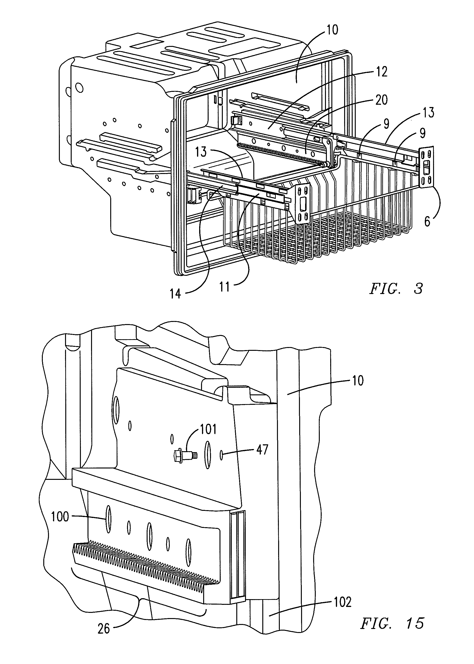
[0094]In a first embodiment with lug (49), the wall (10) has a groove, in which the lug (49) will be inserted. It is necessary to point out that it is not intended that the lug (49) should hold weight or distribute drawer (4) weight over the wall (10) groove. It is possible that the upper part (21) lateral wall (27) fastening means (101) have a length greater than the lug (49) to fasten to the wall (10) groove.

second embodiment

[0095]In a second embodiment without groove (49), as shown in FIG. 20, the drawer mechanism is adaptable to any type of wall (10), independent of whether it has grooves or not. Therefore, in this embodiment, the fastening means (101) in the upper part (21) lateral wall (27) are capable of being inserted in the wall (10). Likewise, the fastening means (101) in the lower part (22) lateral wall (24) are also capable of being inserted in the wall (10). As stated before, it is possible that the locaters (29) rest on the wall, and consequently, also help distribute the drawer (4) weight.

[0096]The fastening means (101), be them of the lower part (22) lateral wall (24) and / or the upper part (21) lateral wall (27), possibly in combination with locaters (29), should make a contrary force (F3) to the basket weight force (F1) and the work (W) done by the rail (3) and basket (4), specifically the basket (4) and its content, be it when the basket (4) is introduced in the drawer or even more so, w...


PUM


Abstract

A cabinet drawer support beam is provided, and may include on an upper part of such beam, a rail or longitudinal sliding mechanism. An alignment mechanism may be fastened to the rail or longitudinal mechanism. The alignment mechanism may include a pinion that runs in the rack of the lower part of the support beam, and the support beam may be fastened to the cabinet wall by way of barrels and / or fasteners. At least two beams per cabinet may be included.

Description

RELATED APPLICATIONS[0001]This application claims priority from Mexican application Serial No. MX / a / 2008 / 005013 filed Apr. 17, 2008, which is incorporated herein by reference in its entirety.FIELD OF THE INVENTION[0002]The present invention refers to a set of support beams along with a drawer mechanism, and its method of assembly, and more particularly, to a mechanism for supporting drawers in a horizontal axis, for cabinets in general, preferably, however not limited to, the field of refrigerators and freezers, as well as an assembly method thereof.BACKGROUND OF THE INVENTION[0003]During the last few years, bottom mount refrigerators, with drawers in their bottom part, have been re-introduced in the market. A refrigerator with a drawer in its lower part has the fresh food compartment placed vertically in the upper part of a drawer or freezing compartment. The freezing compartment is usually smaller than the fresh food compartment.[0004]There are different types of mounting mechanis...

Claims


Application Information

Patent Timeline
Patent Type & Authority Patents(United States)
IPC IPC(8): A47B88/12A47B88/493
CPCA47B88/044A47B88/10A47B2210/0032A47B2210/0059A47B2210/007A47B2210/0078A47B2210/17A47B88/43A47B88/493
Inventor VELARDE, VICTOR GERARDO CABALVELAZQUEZ, ALAN FEDERICO CAMACHOAHUMADA, IGNACIO MARINFERNANDEZ, CARLOS ESPINOSA DE LOS MONTEROS
Owner MABE SA DE CV
Why Eureka
Try Eureka