
Surgical instrument and method of use for inserting an implant between two bones

a surgical instrument and bone technology, applied in the field of inserters, can solve problems such as neurologic impairment and possible permanent damage to surrounding tissue, and achieve the effect of reducing the risk of surgical complications

Active Publication Date: 2012-03-27
AESCULAP IMPLANT SYST
View PDF274 Cites 30 Cited by
  • Summary
  • Abstract
  • Description
  • Claims
  • Application Information

AI Technical Summary

Benefits of technology

"The present invention provides a surgical instrument and method for inserting spinal implants that can be used in patients with missing or damaged vertebral bodies. The instrument has a handle and elongate member with a length control mechanism that allows the surgeon to adjust the length of the implant after it has been placed between the two bones. The instrument also has a gear assembly and drive shaft that extend through a first opening in the handle assembly. The method involves surgically creating an opening on the skin of the patient, obtaining the surgical instrument, and inserting the implant into the space between the two bones. The instrument can be used to adjust the length of the implant and secure it in place. The invention provides a more efficient and effective tool for spinal surgery."

Problems solved by technology

Damage or disease that affects the integral structure of a bone structure or more specifically, a vertebral body within an individual's spinal column may lead to neurologic impairment with possible permanent damage to the surrounding tissue.

Method used


Image

  • Surgical instrument and method of use for inserting an implant between two bones
  • Surgical instrument and method of use for inserting an implant between two bones
  • Surgical instrument and method of use for inserting an implant between two bones

Examples


Embodiment Construction

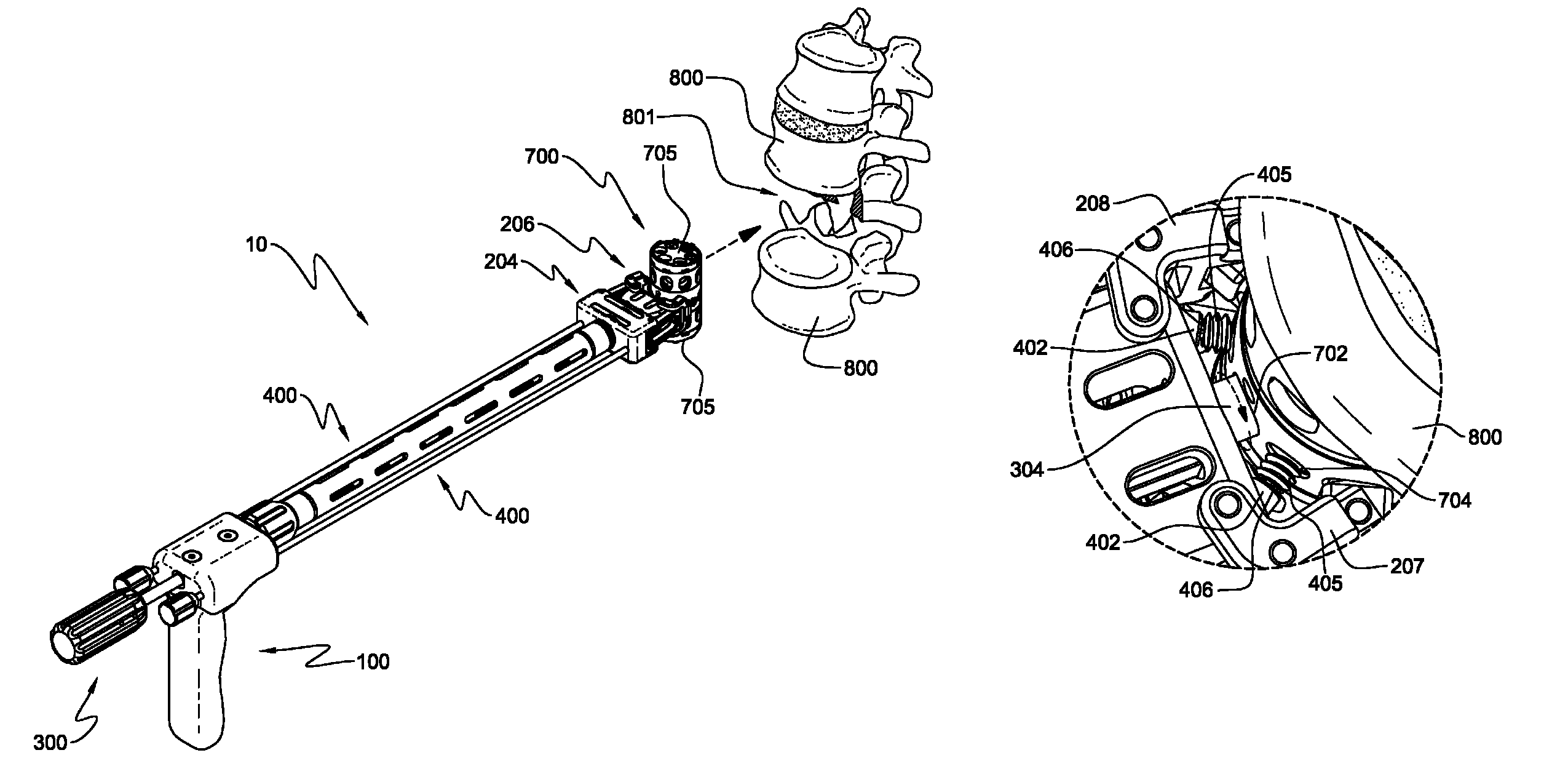
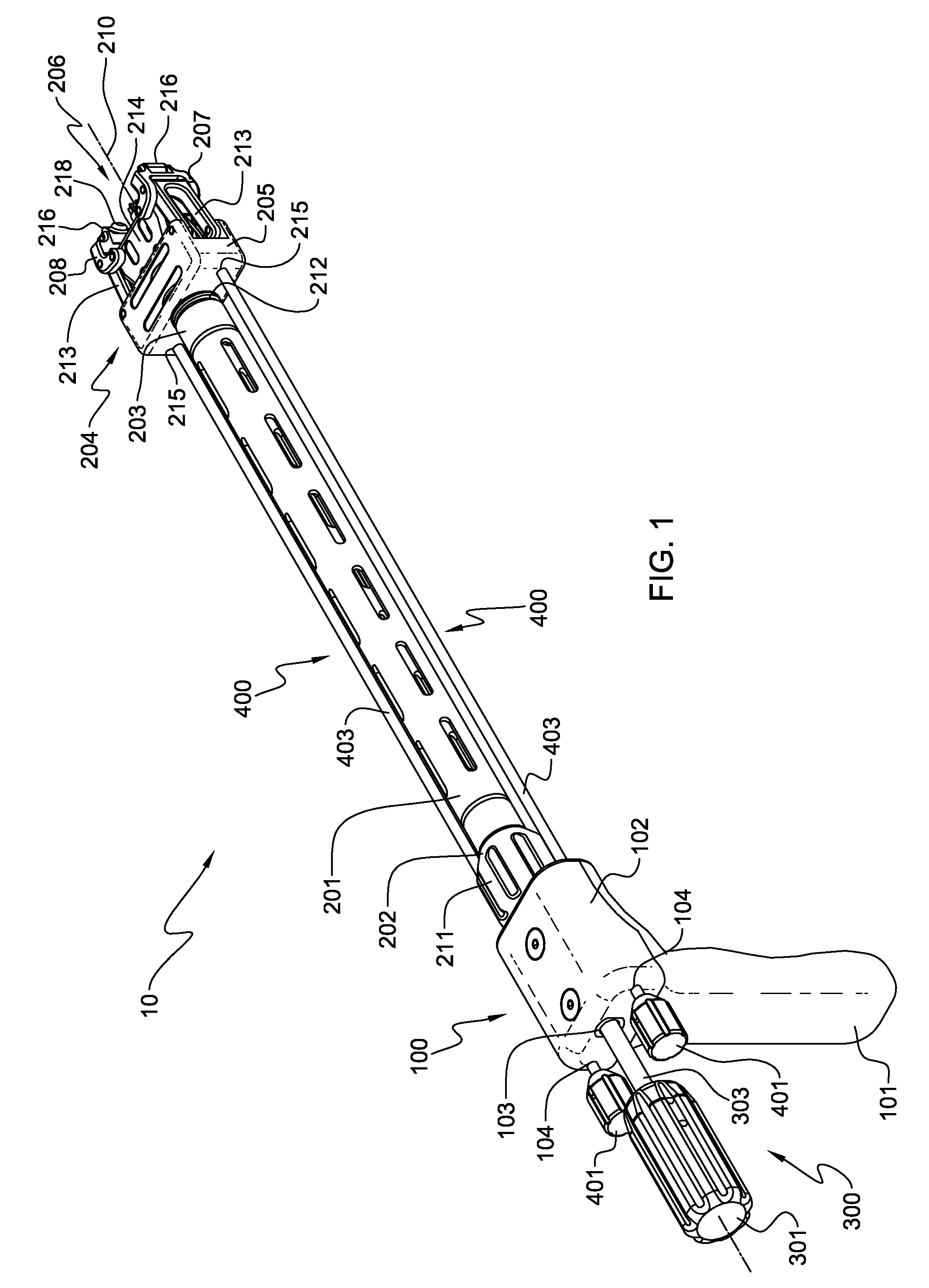
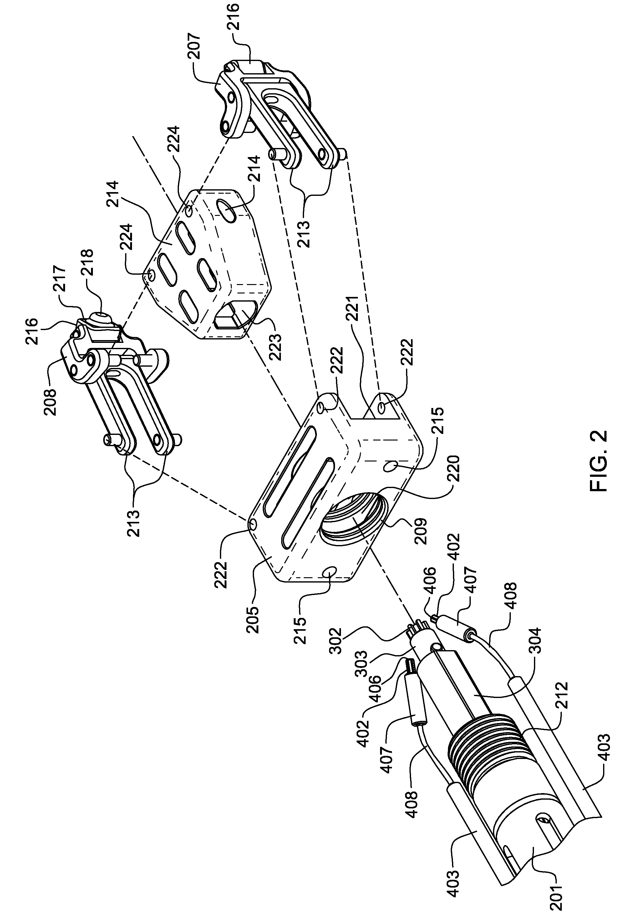
[0025]Generally stated, disclosed herein is a surgical instrument for use in inserting an implant into a space between two bones. More specifically, the surgical instrument will typically be used to hold, extend / contract and lock a vertebral body replacement implant during implantation into the spinal column. The surgical instrument generally includes a handle assembly, an elongate member that includes an implant engagement assembly at the distal end. The implant engagement assembly further includes an actuation body and an implant holding portion that has two arms that move and grasp the implant when the actuation body is actuated. The surgical instrument further includes a length control mechanism and locking mechanism. The distal end or gear assembly of the length control mechanism is inserted into the implant and couples to a corresponding length adjustment mechanism to allow for varying the overall length of the implant. The surgical instrument typically further includes a lock...


PUM


Abstract

The surgical instrument includes a handle assembly and an elongate body that has first and second ends with the first end being located adjacent to the handle assembly and the second end being moveably connected to an implant engagement assembly. The surgical instrument also has a length control mechanism that includes a gripping portion, a drive shaft and a gear assembly. The surgical instrument further has a locking mechanism that includes a gripping portion, a connecting rod and a coupling end. The length control mechanism functions to adjust the overall length of an implant that is held by the implant engagement assembly before being implanted in vivo. The locking mechanism operates to secure the overall length of the implant following final length adjustment and implantation. A surgical method for using the surgical instrument, a method of fabrication and a spinal implant insertion kit is also disclosed.

Description

TECHNICAL FIELD[0001]The present invention relates generally to orthopedic and neurosurgical instrumentation and techniques, and more specifically, but not exclusively, concerns an inserter to be used to implant a device between two bones.BACKGROUND OF THE INVENTION[0002]Damage or disease that affects the integral structure of a bone structure or more specifically, a vertebral body within an individual's spinal column may lead to neurologic impairment with possible permanent damage to the surrounding tissue. Maintaining proper anatomic spacing within a bone structure and the spinal column is critical to ensuring continued functionality of the surrounding tissue and for the spinal column, the spinal cord and nerve roots and therefore, avoidance of long term serious neurological impairment.[0003]Typically, spinal implants that are used as a spacer type of device have a fixed overall length and are implanted without the ability to adjust the degree of expansion or curvature without usi...

Claims


Application Information

Patent Timeline
Patent Type & Authority Patents(United States)
IPC IPC(8): A61B17/58A61F2/00
CPCA61F2/4611A61F2/44A61F2002/30471A61F2002/30507A61F2002/30523A61F2002/3055A61F2220/0091A61F2002/4622A61F2002/4627A61F2002/4628A61F2002/4642A61F2220/0025A61F2002/30616A61F2/4637
Inventor REFAI, DANIELEBERSOLE, JEFFREY T.FARRIS, JEFFREY A.
Owner AESCULAP IMPLANT SYST
Learn More