Device and method for joining and tacking sections for transportation vehicles

a technology for transportation vehicles and parts, applied in the field of manufacturing of parts for transportation vehicles, can solve the problems of increasing production costs, inability to meet the needs of investment-intensive automatic production equipment, and previously known devices and methods that are not suitable for the shape and/or size-dependent formation of sections, so as to achieve the effect of minimizing the retention time of sections in the devi

Active Publication Date: 2012-04-03
AIRBUS OPERATIONS GMBH
View PDF13 Cites 13 Cited by
  • Summary
  • Abstract
  • Description
  • Claims
  • Application Information

AI Technical Summary

Benefits of technology

[0009]In another embodiment of the device, at least one measuring device such as a laser-measuring device, may determine values for the spatial position of at least one individual component. As a result, the spatial positions of the individual components accommodated on the positioning devices may be precisely determined.
[0010]In still another embodiment of the device, at least one control and / or regulating unit is provided. The control and / or regulating unit may allow for coordination and control of all positioning devices.

Problems solved by technology

A special construction site tailored to the respective section to be fabricated must be provided for each section having different geometries, thereby significantly increasing production costs.
In addition, the sections generally remain at the respective construction site in known devices and methods, such that in particular the investment-intensive automatic production equipment are not utilized to capacity during time-consuming manual operations to configure or reconfigure the equipment for sections with different geometries.
Previously known devices and methods are not suitable for the shape and / or size-independent formation of sections for aircraft using at least partially automated production processes.

Method used


Image

  • Device and method for joining and tacking sections for transportation vehicles
  • Device and method for joining and tacking sections for transportation vehicles
  • Device and method for joining and tacking sections for transportation vehicles

Examples


Embodiment Construction

[0040]The same or similar elements are marked with the same reference numbers in the drawings in order to make comparison between the drawings easier.

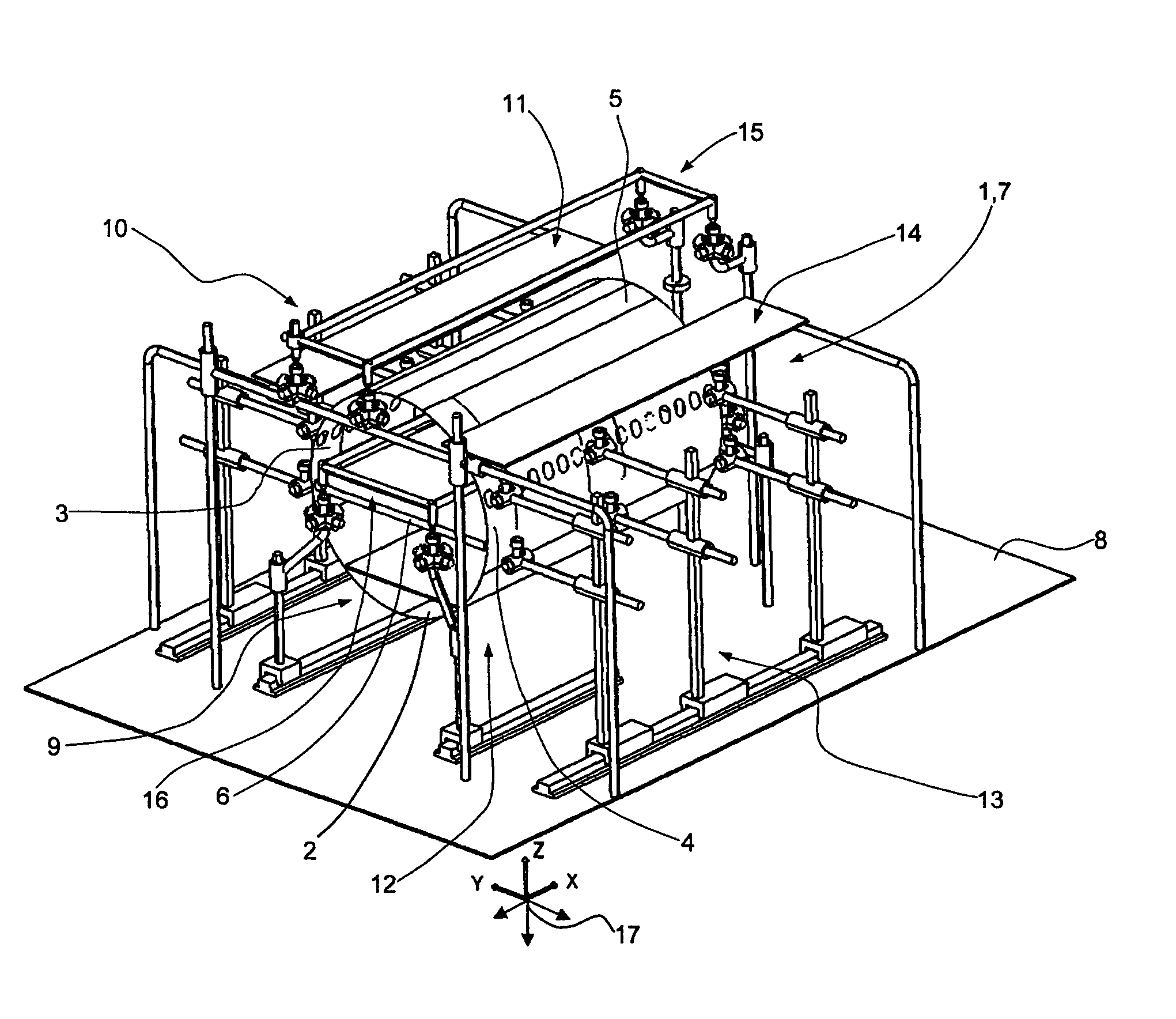
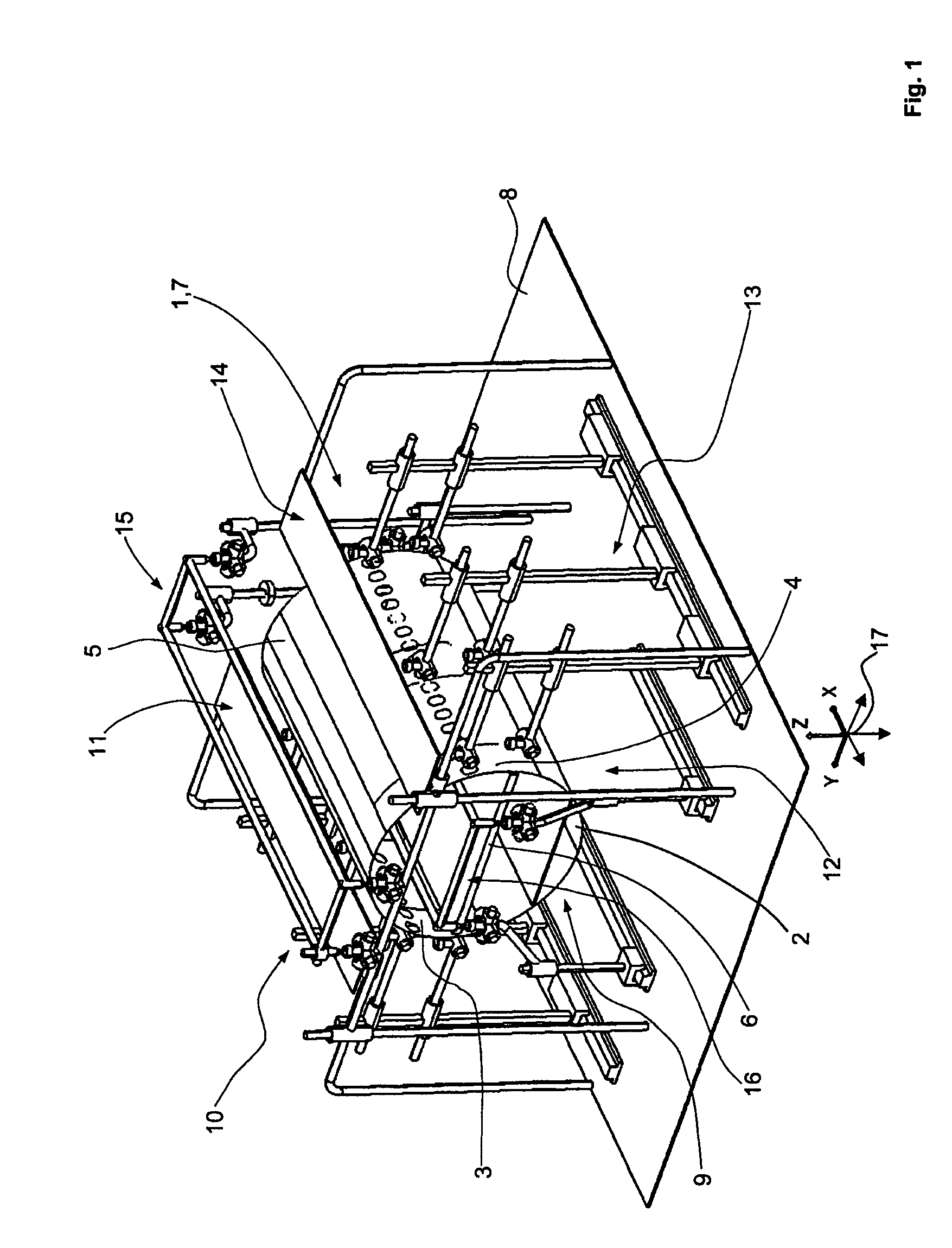
[0041]In FIG. 1, one embodiment of a device is shown in a perspective view with several positioning devices for positioning individual components to join together a section 7. A section 7 formed with several individual components 1, such as a lower shell 2, a left lateral shell 3, a right lateral shell 4, an upper shell 5 and a floor scaffold 6 rests on a positioning device designed as a base positioner, which is known in the art and is not shown in FIG. 1 for the sake of clarity. The base positioner is arranged on a base surface 8 below the section 7. Among other things, the base positioner comprises a positioning rack (also not shown), with an accommodation device for holding and positioning the lower shell 2 relative to the device, and a transportation device. The transportation device may be used to initially move the lower shell 2...


PUM

PropertyMeasurementUnit
shapeaaaaaaaaaa
sizeaaaaaaaaaa
inherent rigidityaaaaaaaaaa

Abstract

A device and method for joining and tacking several individual components independently of shape and / or size to form inherently rigid, transportable sections for transportation vehicles, such as an aircraft is disclosed. According to one embodiment of the invention, the individual components may be spatially positioned relative to each other independently of shape and / or size. The spatial positions of the individual components may be determined by a measuring device, such as a laser measuring device, and varied via several positioning devices until a preset spatial position of the individual components has been reached in which the individual component are tacked together to form a section. In another embodiment, the positioning devices may be designed as base positioners, a first lateral positioner, a second lateral positioner, an upper positioner as well as an inner positioner. Joining and tacking of several individual components 1 may form varying sections such as sections with varying cross sectional geometries and / or cross sectional dimensions and / or linear dimensions for different types of aircraft or for derivatives of the same aircraft types. In addition, the sections may have two working platforms on either side of the section.

Description

RELATED APPLICATION[0001]This application claims the benefit of the filing date of German Patent Application No. 10 2004 056 286.5 filed Nov. 22, 2004, the disclosure of which is hereby incorporated herein by reference.FIELD OF THE INVENTION[0002]The field relates to manufacturing of sections for transportation vehicles, such as aircraft, from component parts.TECHNOLOGICAL BACKGROUND[0003]Devices and methods for forming sections, in particular for aircraft, are known that are each being aligned relative to a section with a specific shape and / or size, in particular with a specific cross sectional geometry or cross sectional dimension and / or linear dimension. A special construction site tailored to the respective section to be fabricated must be provided for each section having different geometries, thereby significantly increasing production costs. In addition, the sections generally remain at the respective construction site in known devices and methods, such that in particular the ...

Claims


Application Information

Patent Timeline
Patent Type & Authority Patents(United States)
IPC IPC(8): B21D53/88B23K1/14B23Q3/00B23C1/00B25B1/20B25B27/14
CPCB64F5/0009Y10T29/5177Y10T29/53961Y10T29/49622Y10T29/53978Y10T29/49895Y10T29/49769B64F5/10
Inventor FRAUEN, HOLGERGNAUCK, TOMASKLEMKOW, EIKE
Owner AIRBUS OPERATIONS GMBH
Why Eureka
Try Eureka