Ultrasonic lens electrode manufacturing method for effectively reducing acoustic parasitic signal

A technology of parasitic signal and production method, which is applied in the direction of material analysis, scientific instruments, and measuring devices using sonic/ultrasonic/infrasonic waves, which can solve the problem of reducing the excitation intensity of sound field radiation, reducing the ultrasonic high-frequency performance of ultrasonic lens design, and the limited space of the lens. Crowding and other problems, to reduce the generation and scattering of additional complex sound sources, improve the quality of microscopic imaging, and facilitate accurate spatial positioning.

Inactive Publication Date: 2017-03-15
UNIV OF SCI & TECH OF CHINA
View PDF5 Cites 2 Cited by
  • Summary
  • Abstract
  • Description
  • Claims
  • Application Information

AI Technical Summary

Problems solved by technology

[0003] 1) The thickness of the metal electrode used as the substrate cannot be made ultra-thin, even reaching the scale of micron millimeters, otherwise it is difficult to ensure that there will be no breakage or cracks during the manufacturing process;
[0004] 2) Too thick electrode metal material will reduce the acoustic-mechanical performance between the transducer and the lens waveguide conduction rod or probe, thus deviating from the transducer (lithium niobate material or zinc oxide and other piezoelectric materials) and The original intention of the conductive rod or probe material matching is to reduce the acoustic coupling performance and reduce the ultrasonic high-frequency performance of the ultrasonic lens design, resulting in frequency attenuation;
[0005] 3) There is still a layer of bonding material between the metal substrate material of the electrode and the material of the waveguide rod or probe, and an extra intermediate link will be added out of thin air to further reduce the acoustic coupling performance of the transducer and the conductive rod ;
[0006] 4) The substrate metal area of ​​the electrode is often made larger than the bottom area of ​​the transducer, so as to facilitate the installation on the electrode and lead out other external guide wires. Such a large area may easily lead to a gap between the lead-out electrode and the metal shell of the lens. The risk of short-circuiting of related circuits due to contact between them will increase the difficulty of processing the metal shell;
[0007] 5) The substrate metal area of ​​the electrode is too large, which makes the limited space inside the lens more crowded, so that the electrode can only be attached to the surface of the transducer for fixation, and the force point of the lead wire also directly acts on the surface, which is easy to cause stress on the transducer and fall off;
[0008] 6) It is difficult to accurately locate the substrate metal of the electrode, the bonding material, the transducer and the conductive rod (or probe) during processing and connection
This is extremely inconvenient for spatial alignment between the transducer and the focusing aperture, resulting in spatial misalignment of the high-frequency sound source and reducing the excitation intensity of the sound field radiation;
[0009] 7) Due to the microscopic misalignment of the substrate metal of the electrode and the transducer, an additional sound source is generated under the electric excitation field, which produces a complex acoustic interaction process for the ultrasonic lens or probe, which constitutes harmful sound waves parasitic inside the ultrasonic lens or probe, Deteriorating the intrinsic electrical signal performance of the ultrasonic lens, generating a large number of ultrasonic parasitic signals, reducing the signal-to-noise ratio of the lens or probe, thereby reducing the signal-to-noise ratio of the ultrasonic microscopic imaging system or other ultrasonic flaw detection systems

Method used


Image

  • Ultrasonic lens electrode manufacturing method for effectively reducing acoustic parasitic signal
  • Ultrasonic lens electrode manufacturing method for effectively reducing acoustic parasitic signal
  • Ultrasonic lens electrode manufacturing method for effectively reducing acoustic parasitic signal

Examples


preparation example Construction

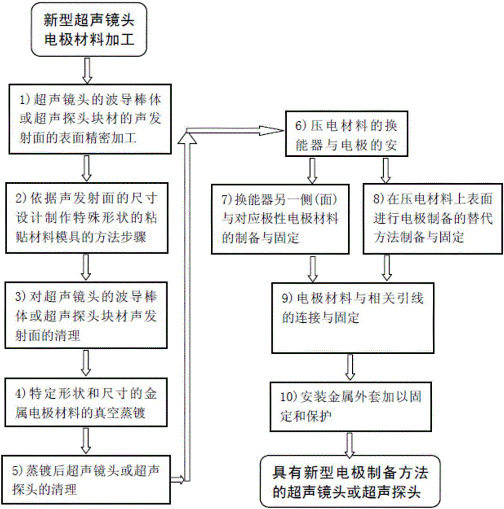
[0045] 4) Preparation and process control of electrode materials with specific shapes and thicknesses;

[0046] 5) Cleaning the evaporated ultrasonic lens or probe and the generated electrode material;

[0047] 6) Install and fix the ultrasonic transducer on the electrode material;

[0048] 7) Preparation and fixation of the electrode material corresponding to the polarity on the other side of the ultrasonic transducer;

[0049] 8) Connection and fixation of the electrode material and its related lead wires;

[0050] 9) The metal jacket is fixed and protected.

[0051]In said step 1, various solid materials such as quartz rods or high molecular polymers are selected as materials for making ultrasonic lenses or acoustic probes, processed into block shapes such as cylindrical rods and wedges, and the rods or blocks are One of the sides is used as the acoustic emission end face, after fine grinding, grinding and other processes to ensure the smoothness ▽≥10.

[0052] In the s...

specific Embodiment

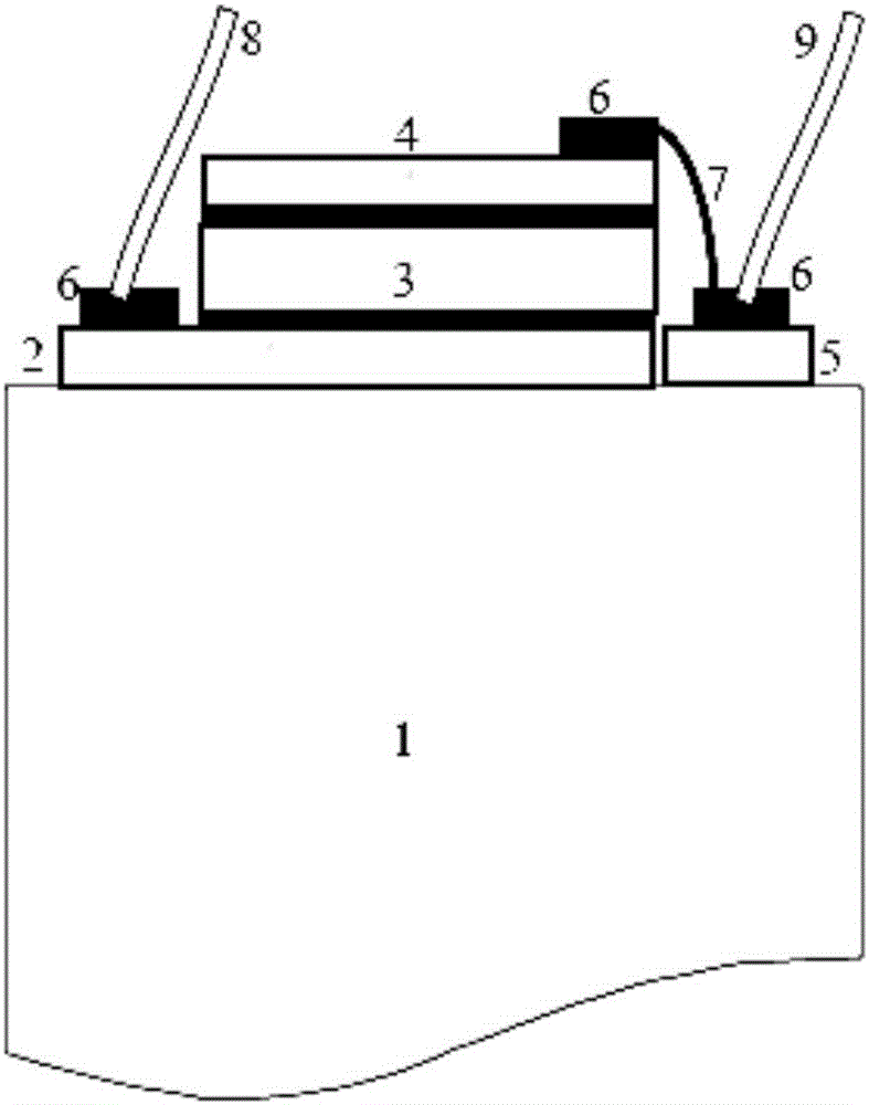
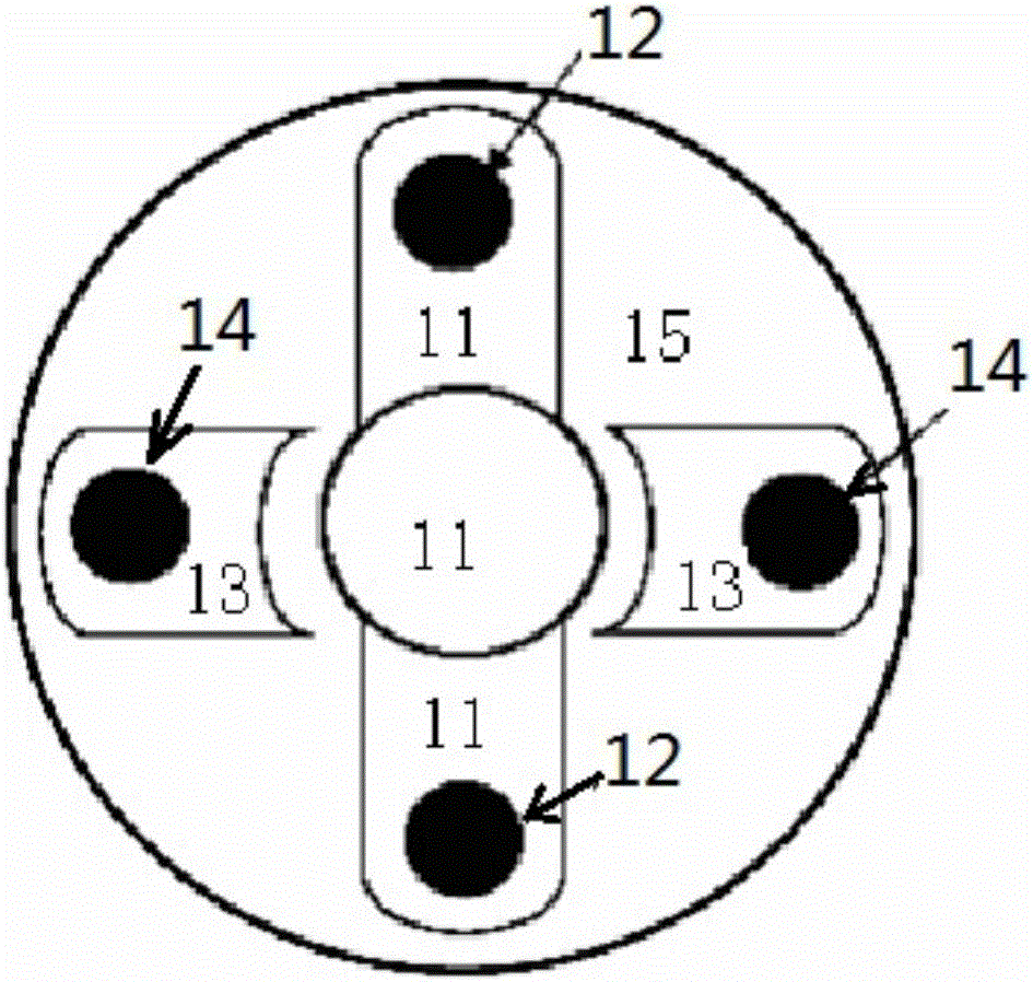
[0127] figure 2 , image 3 Shown is the physical map of the ultrasonic lens obtained through the aforementioned related methods and specific steps. figure 2 A side view entity diagram of the longitudinal rigid connection of the electrode and its attached lead wires with the ultrasonic lens to the rod or ultrasonic probe block is given; image 3 The shape or spatial distribution of the electrode material is given in , which is generally spread out in a cross, and is distributed on the acoustic emission surface of the ultrasonic lens waveguide to the rod or ultrasonic probe block. The combination of the two images provides a complete solution, which can facilitate the production of various ultrasound lenses or ultrasound probes.

[0128] image 3 In , the vapor-deposited electrodes are distributed symmetrically up, down, left, and right. The part symmetrically distributed up and down (labeled 11) is used as the bottom lead-out electrode of the piezoelectric material, and t...


PUM

PropertyMeasurementUnit
lengthaaaaaaaaaa
diameteraaaaaaaaaa
widthaaaaaaaaaa

Abstract

The invention discloses an ultrasonic lens electrode manufacturing method for effectively reducing an acoustic parasitic signal. The method comprises the following steps: processing an acoustic emission surface of a waveguide rod or block of an ultrasonic lens and related acoustic probes; manufacturing and preparing an electrode mold of a special shape according to the size of the acoustic emission surface; cleaning the acoustic emission surface of the waveguide rod or the probe block of the ultrasonic lens and related acoustic probes; preparing an electrode material with a specific shape; cleaning an evaporated ultrasonic lens or probe; mounting and fixing an ultrasonic transducer; preparing and fixing an electrode material of a corresponding polarity on the other side of the ultrasonic transducer; connecting and fixing the electrode material with a related lead; and mounting a metal sleeve for fixation and protection. By adopting the ultrasonic lens electrode manufacturing method, the parasitic signal can be effectively reduced, and the microscopy quality of an ultrasonic microscope system can be improved.

Description

technical field [0001] The invention relates to an electrode manufacturing method of an ultrasonic lens or an ultrasonic probe that is used in ultrasonic detection technology, especially ultrasonic microscope and imaging application technology, and effectively reduces acoustic spurious signals. Background technique [0002] In the prior art, when making ultrasonic lenses or ultrasonic probes and their transducers, although metal materials such as gold and silver may also be used as electrode materials, the waveguide conducting rods or probes and lead wires of the transducers and lenses are often bonded by material adhesion. The physical connection is carried out in sequence, and the area of ​​the electrode is required to be relatively large, so as to provide a relatively strong substrate for the transducer. This approach creates the following problems: [0003] 1) The thickness of the metal electrode used as the substrate cannot be made ultra-thin, even reaching the scale o...

Claims


Application Information

Patent Timeline
Patent Type & Authority Applications(China)
IPC IPC(8): G01N29/22G01N29/24G01N29/32
CPCG01N29/22G01N29/2437G01N29/32G01N2291/101
Inventor 丁锦文李康陈俊华武其亮丁瀚郝绿原
Owner UNIV OF SCI & TECH OF CHINA
Why Eureka
Try Eureka