Grab bar for a waste container

a waste container and grab bar technology, applied in the field of waste containers, can solve the problems of adding cost, unfavorable puncture in the side of the cart, and additional pieces may also be lost, and achieve the effect of convenient and safe installation and removal

Inactive Publication Date: 2012-04-03
CASCADE ENG
View PDF4 Cites 11 Cited by
  • Summary
  • Abstract
  • Description
  • Claims
  • Application Information

AI Technical Summary

Benefits of technology

[0007]Preferably, the retaining structure includes a snap element and a flange that both extend radially outwardly beyond the outer surface of the grab bar. The snap element is positioned near the retention end of the grab bar and is adapted to travel between an extended position and a depressed position. The flange is positioned between the snap element and the free-sliding end of the grab bar. As the bar is installed in the container, an edge of the second opening presses the snap element into the depressed position to allow the grab bar to pass through. The snap element returns to the extended position after it exits the opening, so that a portion or section of the container wall is positioned between the snap element and the flange. In this configuration, the flange prevents the grab bar from being pushed further through the opening, and the snap element prevents the grab bar from being pulled out of the opening, such that the grab bar is securely retained to the container.
[0008]Thus, the grab bar of the present invention can be securely and reliably joined with a waste cart to withstand the rough handling by the automated lifting equipment on a waste truck. The connection feature eliminates the need for the bar to be so long that the ends of the bar nearly touch the inner surfaces of the sides of the cart. Thus, the ends of the grab bar will not be forced through the sides of the cart when the cart is squeezed. Additionally, the bar can be formed in one piece, which eliminates the need for separate clips or pins or any other additional pieces. Further, the bar can be more easily and safely installed and removed from the cart, and can be interchanged with other replacement bars or replacement carts.

Problems solved by technology

However, when the arms on the truck machinery grasp the sides of the cart, the arms may squeeze the cart so tightly that the ends of the bar are forced through the sides of the cart, thus creating undesirable punctures in the sides of the cart.
However, the clips and pins create additional pieces that must be manufactured, inventoried, and installed, thus adding cost.
These additional pieces may also be lost, rendering the bar useless without them.

Method used


Image

  • Grab bar for a waste container
  • Grab bar for a waste container
  • Grab bar for a waste container

Examples


Embodiment Construction

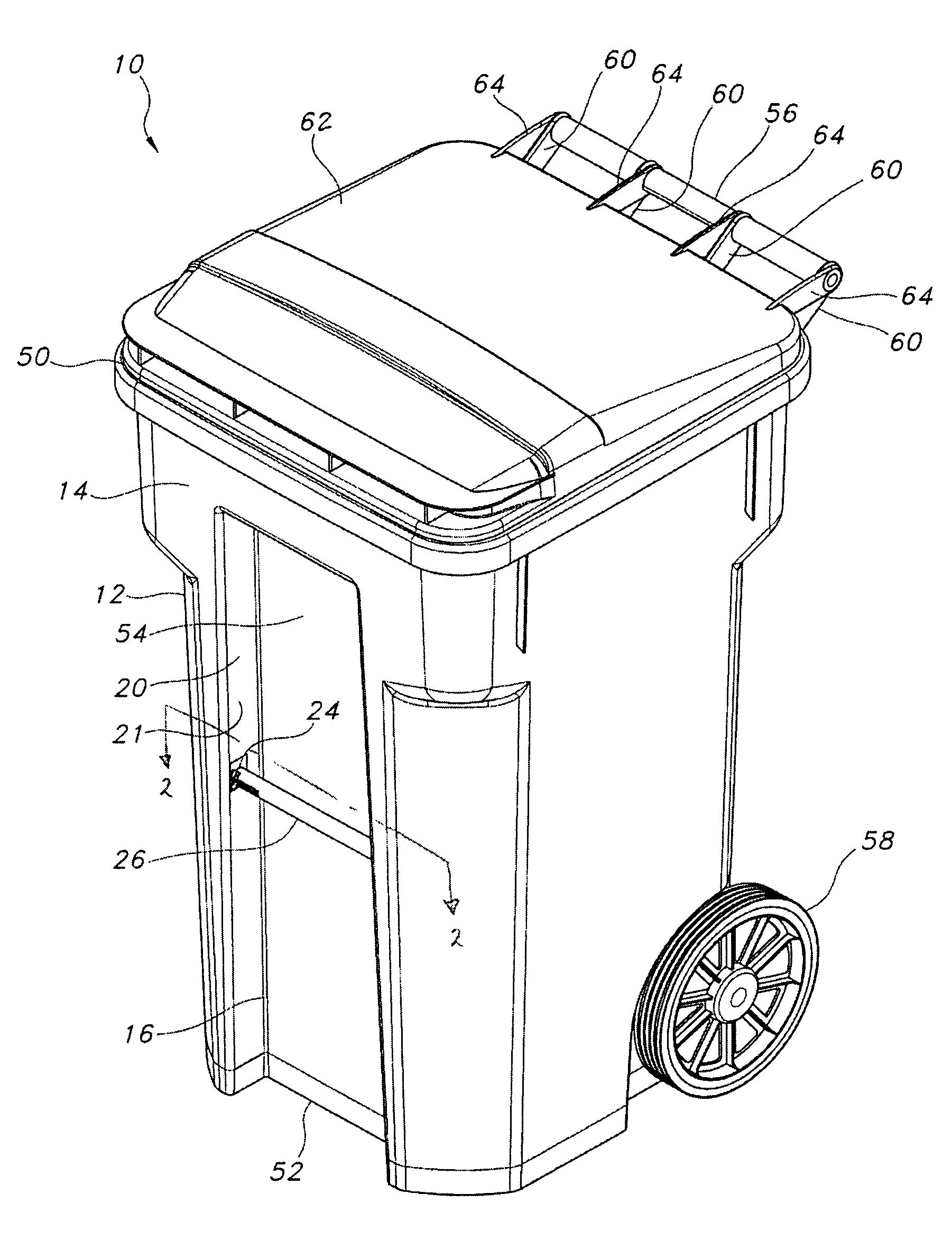
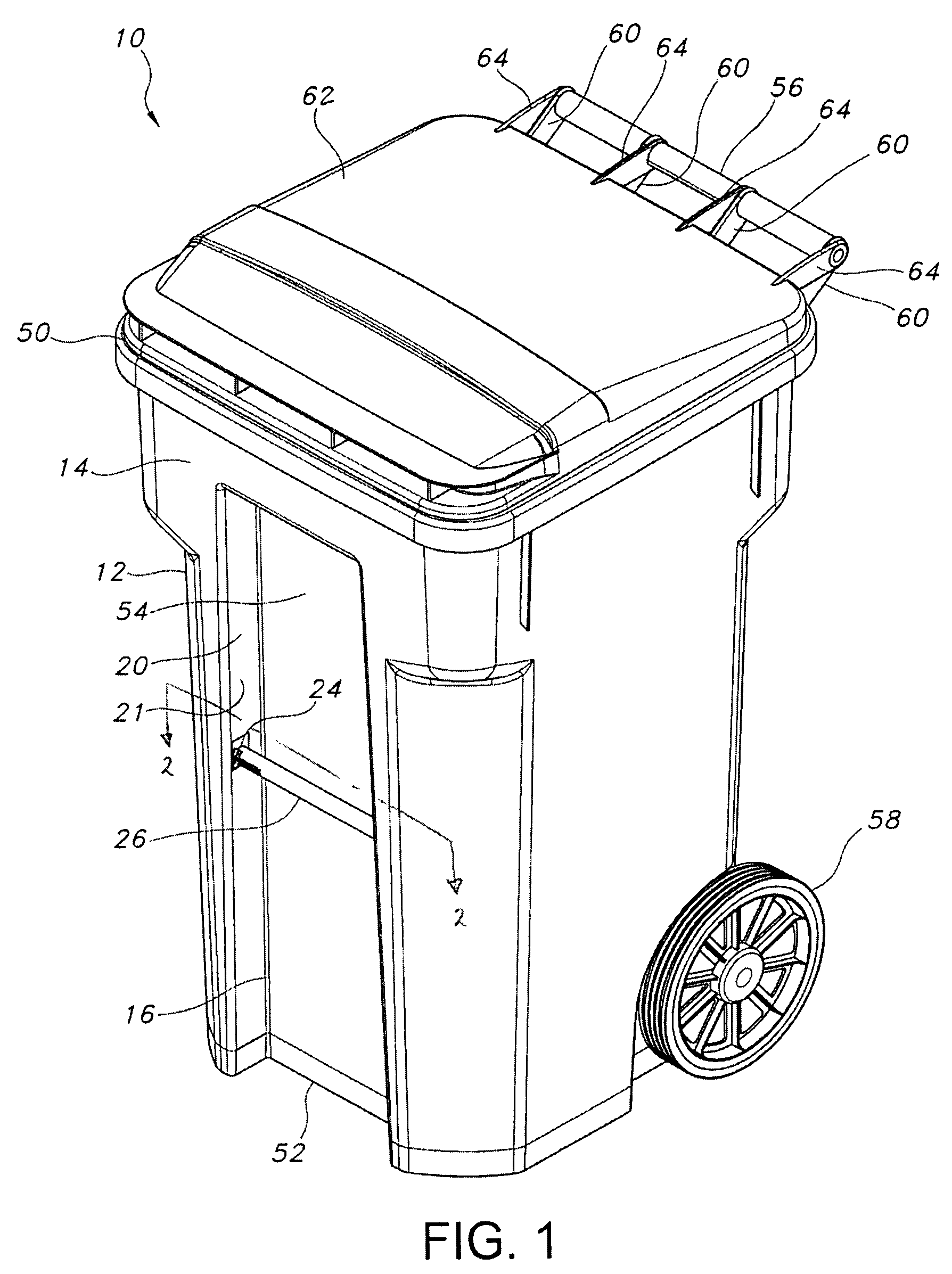
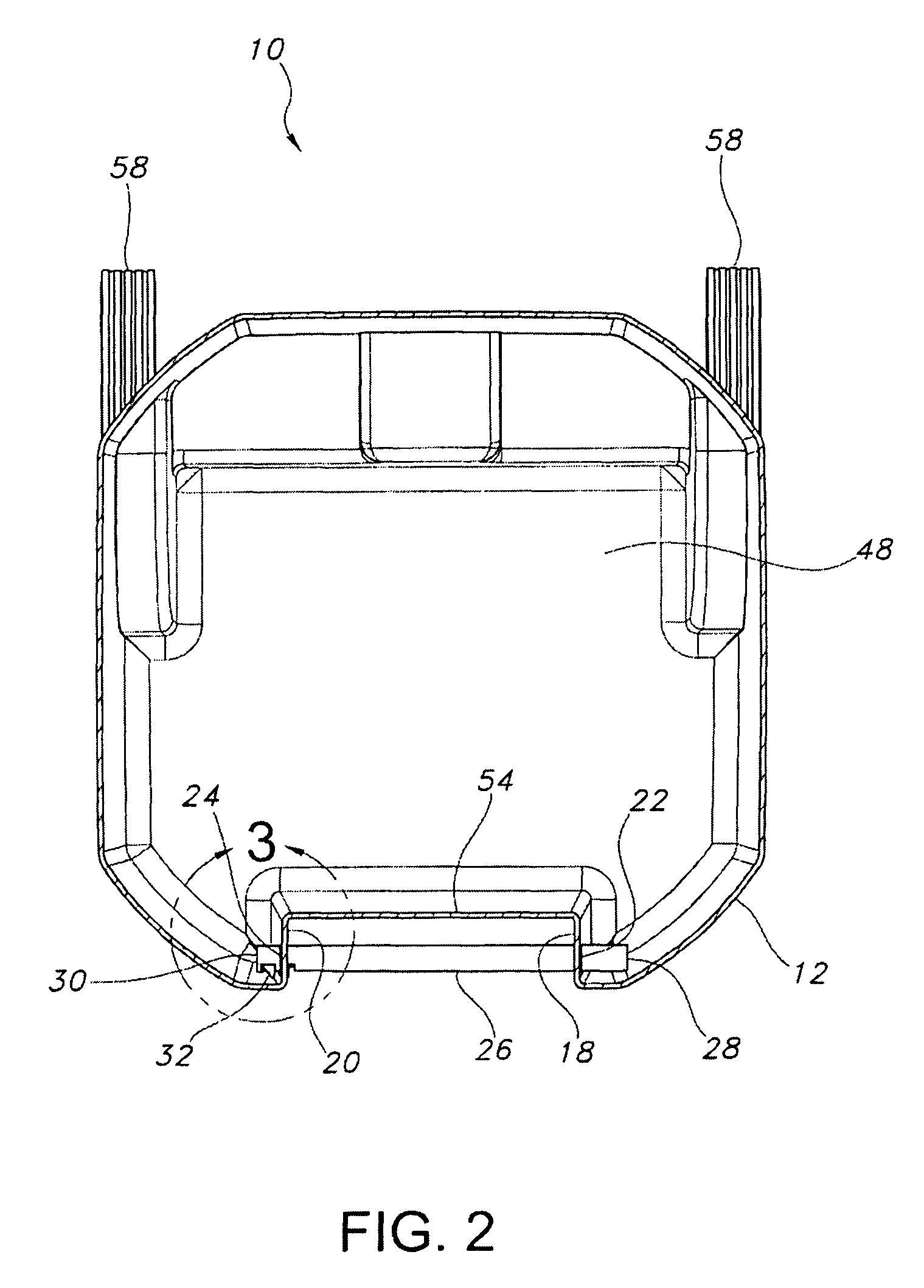
[0018]A wheeled waste container or cart is shown in FIG. 1 and is generally designated 10. The cart 10 includes a container 12 having a front wall 14, with a pocket 16 formed in an outer surface of the wall 14. As shown in FIG. 2, the pocket 16 includes a first sidewall 18 that faces a second sidewall 20. The first sidewall 18 defines an opening 22, and the second sidewall 20 defines an opening 24. The cart 10 includes a grab bar 26 having a free-sliding end 28 and a retention end 30. The length of the grab bar 26 from the free-sliding end 28 to the retention end 30 is longer than the width of the pocket 16 from the first sidewall 18 to the second sidewall 20. The free-sliding end 28 of the grab bar 26 is inserted through the opening 22 in the first sidewall 18, at least until the retention end 30 can be inserted through the opening 24 in the second sidewall 20. The retention end 30 is adapted to join the grab bar 26 with the second sidewall 20 and can do so in any suitable manner.

[...


PUM

PropertyMeasurementUnit
lengthaaaaaaaaaa
widthaaaaaaaaaa
movementaaaaaaaaaa

Abstract

A waste cart includes a container having a wall, with a pocket formed in an outer surface of the wall that creates a first sidewall facing a second sidewall, with an opening formed in both sidewalls. A grab bar has a free-sliding end and a retention end. The free-sliding end is inserted through the opening in the first sidewall, and the retention end is inserted through the opening in the second sidewall. The retention end includes a retainer for securing the grab bar with respect to the second sidewall. In the current embodiment, the grab bar includes a snap element near the retention end and a flange portion between the snap element and the free-sliding end. When the grab bar is installed, a portion of the second sidewall is positioned between the snap element and the flange portion.

Description

BACKGROUND OF THE INVENTION[0001]The present invention relates to waste containers, and more particularly to waste containers including grab bars.[0002]Wheeled waste carts and other waste containers are well known and are commonly used in residential areas. The bags of waste that a resident accumulates throughout a given week are typically stored in a waste cart. On a scheduled day, the resident will wheel the cart containing the waste bags down to the curb for pickup by a waste truck so that the contents of the waste cart can be dumped into the truck. The dumping may occur manually or using machinery on the truck that is adapted to automatically lift the waste cart, turn the cart over and dump its contents into the truck. On some trucks, the machinery includes arms that grasp and squeeze the sides of the cart. On other trucks, the machinery includes a hook or gripper that interfits with a handle or grab bar on the cart.[0003]The grab bar is typically formed from metal, fiberglass o...

Claims


Application Information

Patent Timeline
Patent Type & Authority Patents(United States)
IPC IPC(8): B65D35/32
CPCB65F1/122B65F1/1468Y10T29/49826B65F2220/12Y10S220/908B65F2250/11
Inventor PARKER, BRIAN G.BARRETT, MICHAEL A.KOOIKER, LARRY
Owner CASCADE ENG
Why Eureka
Try Eureka