Interface circuit

a technology of interface circuit and interface, applied in the field of interface circuit, can solve problems such as unnecessary costs being accrued

Active Publication Date: 2012-04-03
HON HAI PRECISION IND CO LTD
View PDF5 Cites 0 Cited by
  • Summary
  • Abstract
  • Description
  • Claims
  • Application Information

AI Technical Summary

Benefits of technology

[0004]A smart card interface circuit is implemented in an electronic device having a smart card reader. A processor of the electronic device is in communication with the smart card reader through the smart card interface circuit. The smart card interface circuit is installed in a dedicated smart card chip, such as Philips Semiconductors' TDA8024. However, the dedicated chip includes functions unnecessary to the electronic device, resulting in unnecessary costs being accrued.

Problems solved by technology

However, the dedicated chip includes functions unnecessary to the electronic device, resulting in unnecessary costs being accrued.

Method used


Image

  • Interface circuit
  • Interface circuit
  • Interface circuit

Examples


Embodiment Construction

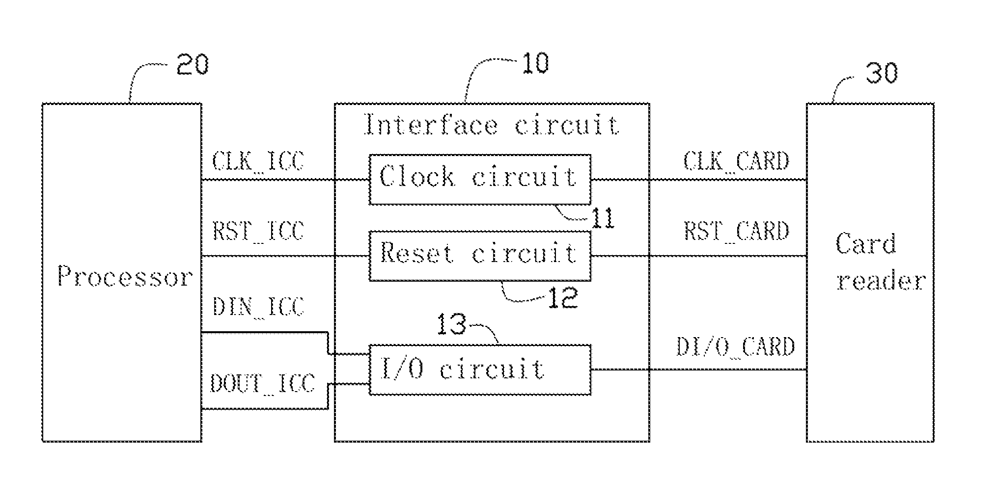
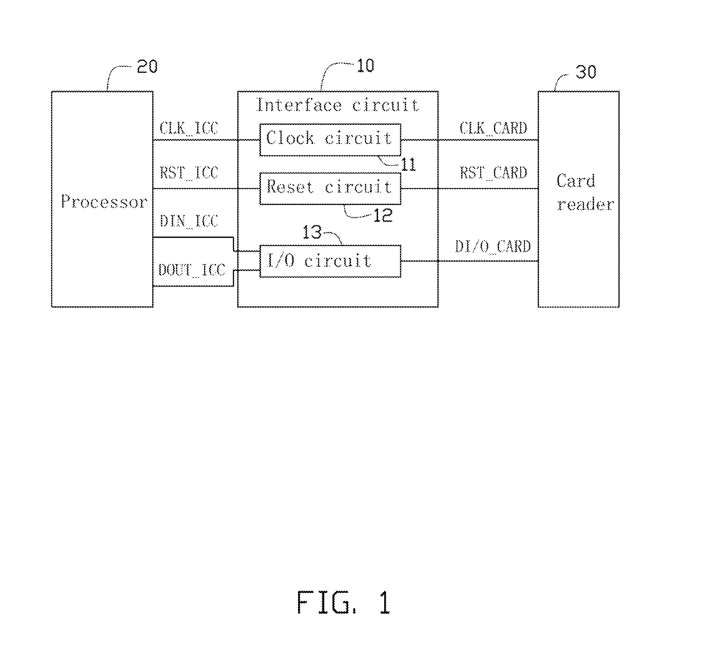
[0009]FIG. 1 is a block diagram of one embodiment of an interface circuit 10 of an electronic device (not shown). The electronic device includes a processor 20 and a card reader 30. The interface circuit 10 electronically connects to the processor 20 and the card reader 30. The electronic device may be a mobile phone, a computer, or a set-top box (STB), for example. The interface circuit 10 includes a clock circuit 11, a reset circuit 12, and an I / O circuit 13. The processor 20 includes a clock pin CLK_ICC, a reset pin RST_ICC, a data input pin DIN_ICC, and a data output pin DOUT_ICC. The card reader 30 includes a clock pin CLK_CARD, a reset pin RST_CARD, and a data I / O pin DI / O_CARD. The clock circuit 11 electronically connects the clock pin CLK_ICC and the clock pin CLK_CARD. The reset circuit 12 electronically connects the reset pin RST_ICC and the reset pin RST_CARD. The I / O circuit 13 electronically connects the data input pin DIN_ICC, the data output pin DOUT_ICC, and the data...


PUM


Abstract

An interface circuit electronically connects a processor and a card reader. The interface circuit includes a clock circuit, a reset circuit, and an I / O circuit. The clock circuit may transmit a clock signal transmitted from the processor to the card reader, and includes a first bipolar junction transistor (BJT). The reset circuit may transmit a reset signal transmitted from the processor to the card reader, and includes a second BJT. The I / O circuit may transmit data transmitted from the processor to the card reader, and includes a third BJT and a fourth BJT.

Description

BACKGROUND[0001]1. Technical Field[0002]The present disclosure relates to an interface circuit electronically connecting a processor and a card reader.[0003]2. Description of Related Art[0004]A smart card interface circuit is implemented in an electronic device having a smart card reader. A processor of the electronic device is in communication with the smart card reader through the smart card interface circuit. The smart card interface circuit is installed in a dedicated smart card chip, such as Philips Semiconductors' TDA8024. However, the dedicated chip includes functions unnecessary to the electronic device, resulting in unnecessary costs being accrued.BRIEF DESCRIPTION OF THE DRAWINGS[0005]FIG. 1 is a block diagram of one embodiment of an interface circuit of an electronic device.[0006]FIG. 2 is a circuit diagram of one embodiment of a clock circuit of FIG. 1.[0007]FIG. 3 is a circuit diagram of one embodiment of a reset circuit of FIG. 1.[0008]FIG. 4 is a circuit diagram of on...

Claims


Application Information

Patent Timeline
Patent Type & Authority Patents(United States)
IPC IPC(8): H03K19/0175
CPCG06K7/0008
Inventor CHIANG, HUANG-YU
Owner HON HAI PRECISION IND CO LTD
Why Eureka
Try Eureka