Method for digital noise reduction in low light video

a low-light video and digital noise technology, applied in the field of video production, can solve the problems of low false alarm rate for video analytics and motion triggered recording, poor visual clarity, and noisy video acquired under low-light conditions, and achieve the effects of reducing luminance noise, noise reduction, and chrominance noise reduction

Active Publication Date: 2012-04-03
HONEYWELL INT INC
View PDF16 Cites 30 Cited by
  • Summary
  • Abstract
  • Description
  • Claims
  • Application Information

AI Technical Summary

Benefits of technology

[0020]An embodiment of the present invention separating a video frame into luminance channel data and chrominance channel data; filtering the chrominance channel data to reduce chrominance noise and the luminance channel data to reduce luminance noise; combining the filtered chrominance channel data and the filtered luminance channel data to generate a first filtered output; blending the first filtered output with a second filtered output generated from a previous video frame to generate a noise-reduced video.

Problems solved by technology

Video acquired under low light condition is often noisy and of poor visual clarity.
The noise filtering also results in lower false alarm rate for video analytics and motion triggered recording.
Noise is a component of any digital video, however, noise is more apparent in low light conditions over homogeneous regions.
This inherent randomness in incident photon gives rise to photon noise.
Other sources of noise in surveillance video are thermal noise or dark current, defective sensing elements, quantization error, compression error and transmission error.
A problem with this approach is that motion areas in the picture (which can often be of greater interest than the static background) appear blurred as a result of the long integration time.
Excessive filtering results in loss of image structure, whereas minimal filtering leaves behind traces of residual noise.
One of the challenges in local filtering for noise removal is removing image noise while preserving the image structures.
However these methods are computationally intensive.

Method used


Image

  • Method for digital noise reduction in low light video
  • Method for digital noise reduction in low light video
  • Method for digital noise reduction in low light video

Examples


Embodiment Construction

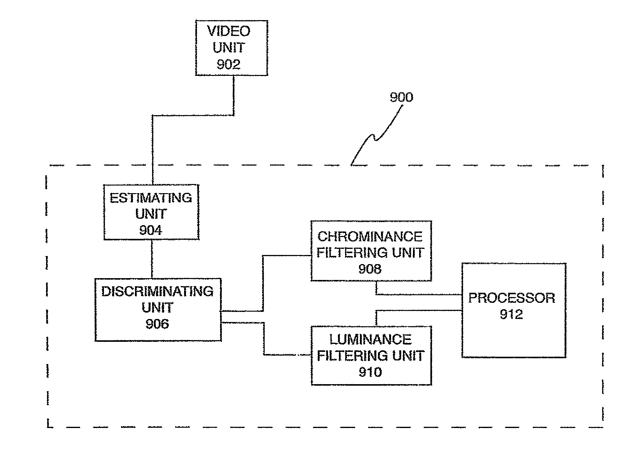
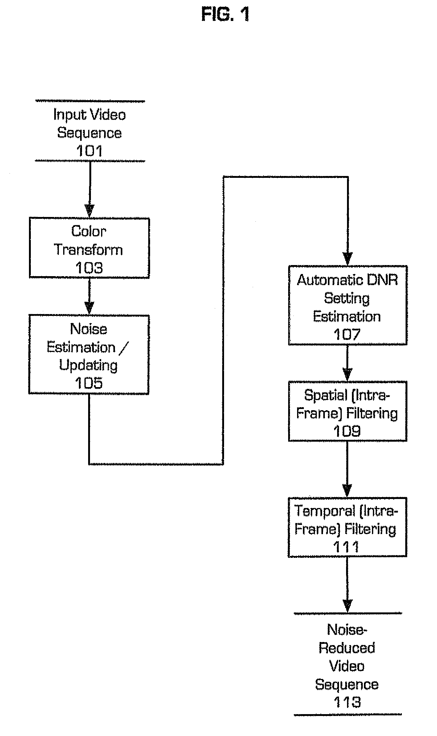
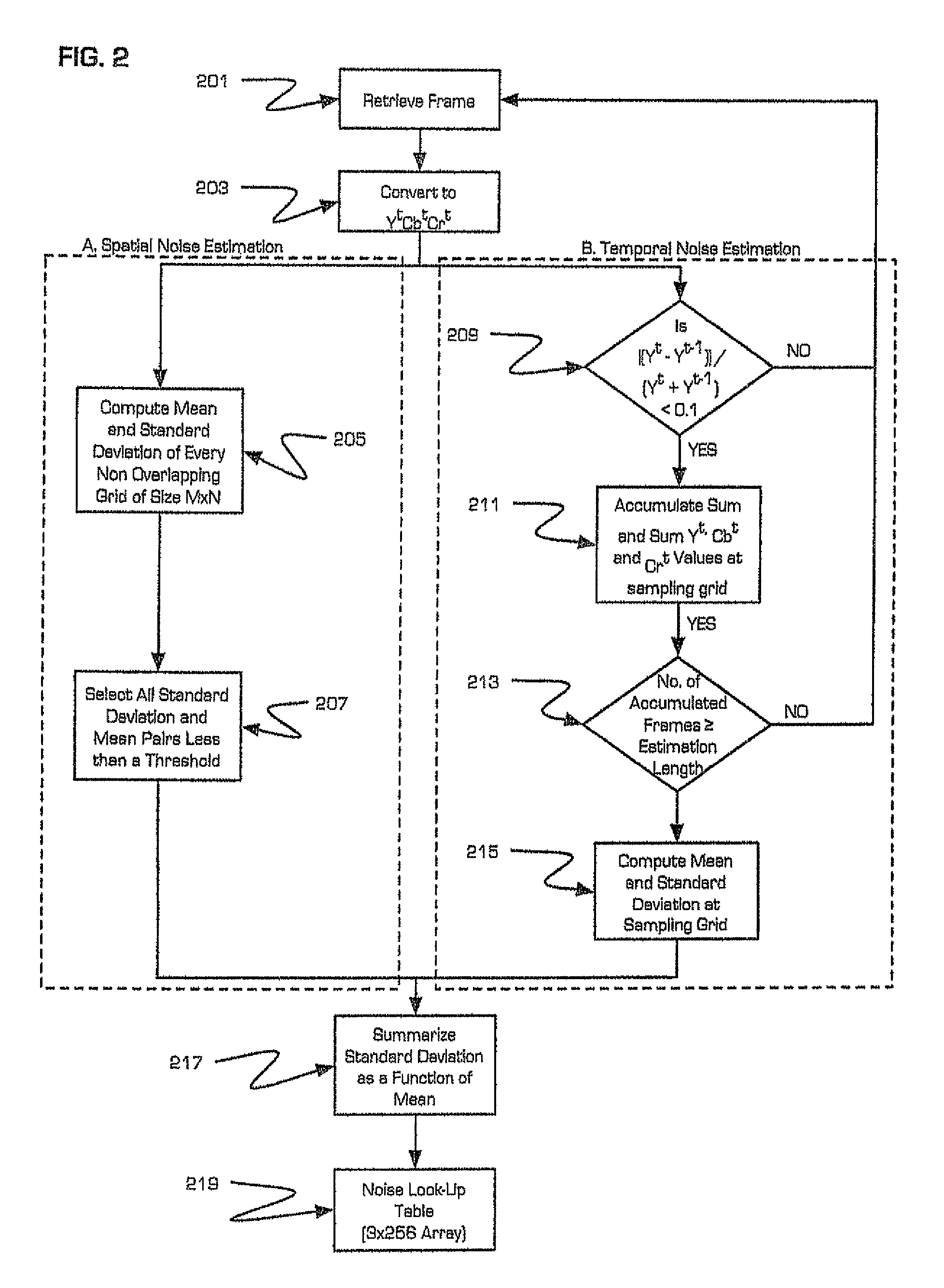
[0034]The present invention implements a method for digital noise reduction that makes use of both intra-frame and inter-frame filtering. An intensity dependent noise model that is derived from a sequence of video frames controls the filter settings and filter parameters. The noise reduction algorithm of the present invention can ran in a standard PC environment at real time speed without taking recourse to specialized hardware. However, the preferred implementation is to host the noise-filtering module of the present invention within a digital signal processor (DSP) core. Such a DSP can be incorporated into a digital video recorder or in an intermediate device disposed between a video capture device and a video recording device.

[0035]DNR filtering is suitable for a variety of application scenarios. By implementing the DNR algorithm in a PC environment, it can be used to display noise free video while retrieving archived noisy video.

[0036]Alternatively, DNR filtering can be applied ...


PUM


Abstract

A system and method for filtering video noise is provided. Video generated under low lighting conditions is susceptible to increased noise and graininess, which increases the required storage space required for recording the noisy video. The provided system and method for filtering video noise reduces noise in low-light video by estimating the noise profile associated with at least one video frame; discriminating between chrominance noise and luminance noise in said noise profile; applying predetermined filter criteria to said chrominance noise to estimate the parameters for luminance noise filtering; applying said luminance noise filtering parameters to filter the luminance noise; and generating a first filtered output of a frame by logical combination of outputs obtained from luminance noise filter and chrominance noise filter.

Description

FIELD OF THE INVENTION[0001]The present invention relates generally to video production, and more specifically the present invention relates to a method for digital noise reduction (DNR) in low light video.BACKGROUND OF THE INVENTION[0002]Video acquired under low light condition is often noisy and of poor visual clarity. A much higher bitrate is required to store these noisy videos than for storing noise-free video. Hence, application of noise filtering is a fundamental low level preprocessing step for any video acquired under low light. The noise filtering also results in lower false alarm rate for video analytics and motion triggered recording. It has been observed that even under normal illumination condition wherein noise may not be visually apparent; application of noise reduction filter brings in significant savings in bitrate.[0003]Noise is a component of any digital video, however, noise is more apparent in low light conditions over homogeneous regions. Even under constant i...

Claims


Application Information

Patent Timeline
Patent Type & Authority Patents(United States)
IPC IPC(8): H04N5/00H04N5/217H04N9/64
CPCG06T5/50H04N5/21H04N5/357H04N9/045H04N9/646G06T5/002G06T5/20G06T2207/10016G06T2207/10024G06T2207/20182G06T2207/20192H04N25/60
Inventor MOHANTY, KAMINI KANTARAO, VENKATAGIRI SUBBARAYAWILSON, JEREMY CRAIG
Owner HONEYWELL INT INC
Why Eureka
Try Eureka