
Method for manufacturing a bearing shell assembly, and bearing shell assembly for a ball joint

a technology of bearing shell and assembly, which is applied in the direction of manufacturing tools, couplings, other domestic objects, etc., can solve the problems of complex injection molding technique, large effort involved in the construction of the extension as a latching element, and the formation of radial detent noses at the free end of the extension, etc., to achieve simple and reliable mechanical deformation, favorable energy-saving production, and favorable production effect of the bearing shell assembly

Active Publication Date: 2012-04-10
THK RHYTHM AUTOMOTIVE GMBH
View PDF16 Cites 15 Cited by
  • Summary
  • Abstract
  • Description
  • Claims
  • Application Information

AI Technical Summary

Benefits of technology

"The invention is a method for manufacturing a bearing shell assembly for a ball joint, which involves a plastic extension that is used to connect a spring element to the bearing shell. The plastic extension is easily deformed, allowing for a simple and reliable connection between the spring element and the bearing shell. This method is cost-effective and energy-efficient. The invention also includes a bearing shell assembly produced using this method, which is simple and reliable to use."

Problems solved by technology

The wear occurring over the lifespan of a radial ball joint can lead to the ball joint causing noises during travel, caused by free play in the joint.
However, specifically in the case of a preferred production of the bearing shell as an integral injection molded plastic part, the construction of the extension as a latching element involves considerable effort.
In particular, the provision of notches for the formation of radially movable detent arms and also the forming of an undercut on the detent arms for the formation of radial detent noses at the free end of the extension is complex with regard to injection-molding technique.

Method used


Image

  • Method for manufacturing a bearing shell assembly, and bearing shell assembly for a ball joint
  • Method for manufacturing a bearing shell assembly, and bearing shell assembly for a ball joint
  • Method for manufacturing a bearing shell assembly, and bearing shell assembly for a ball joint

Examples


Embodiment Construction

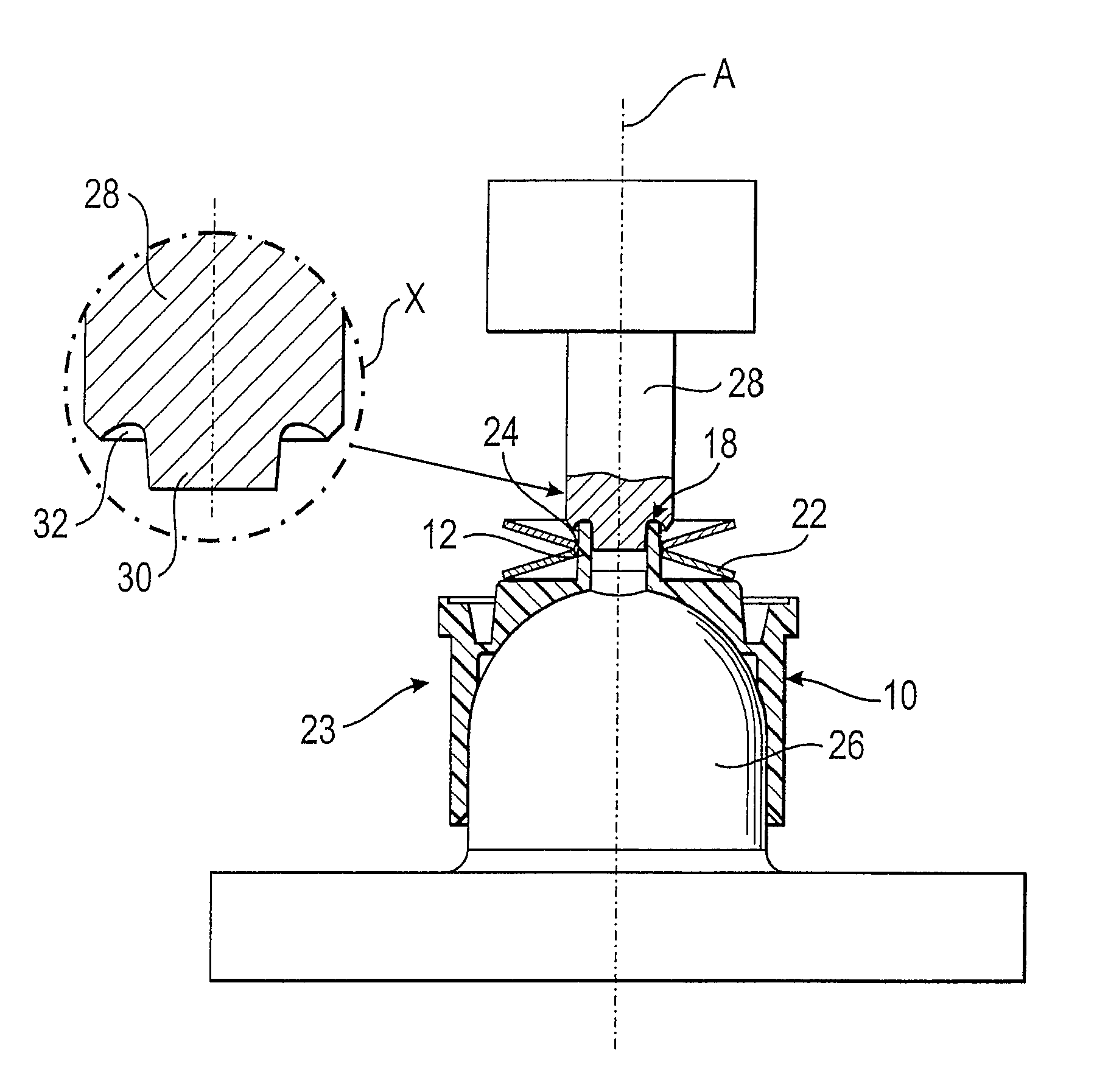
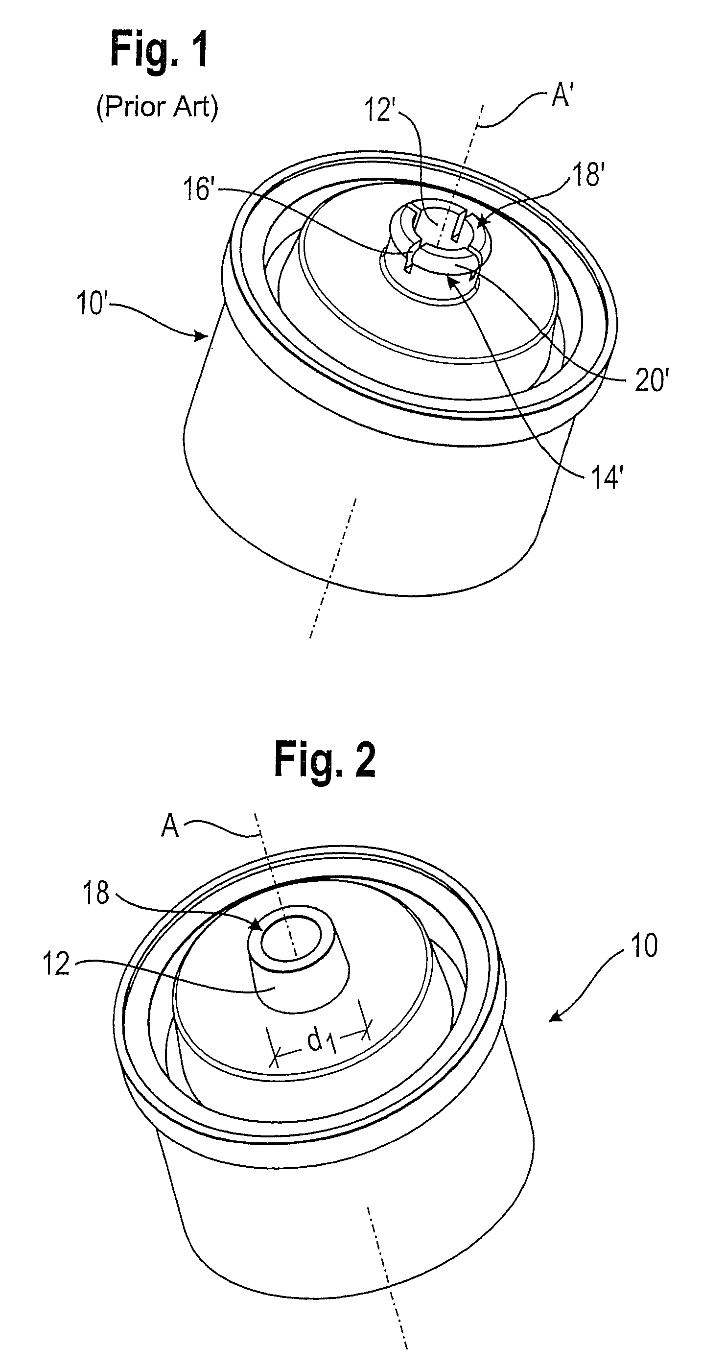
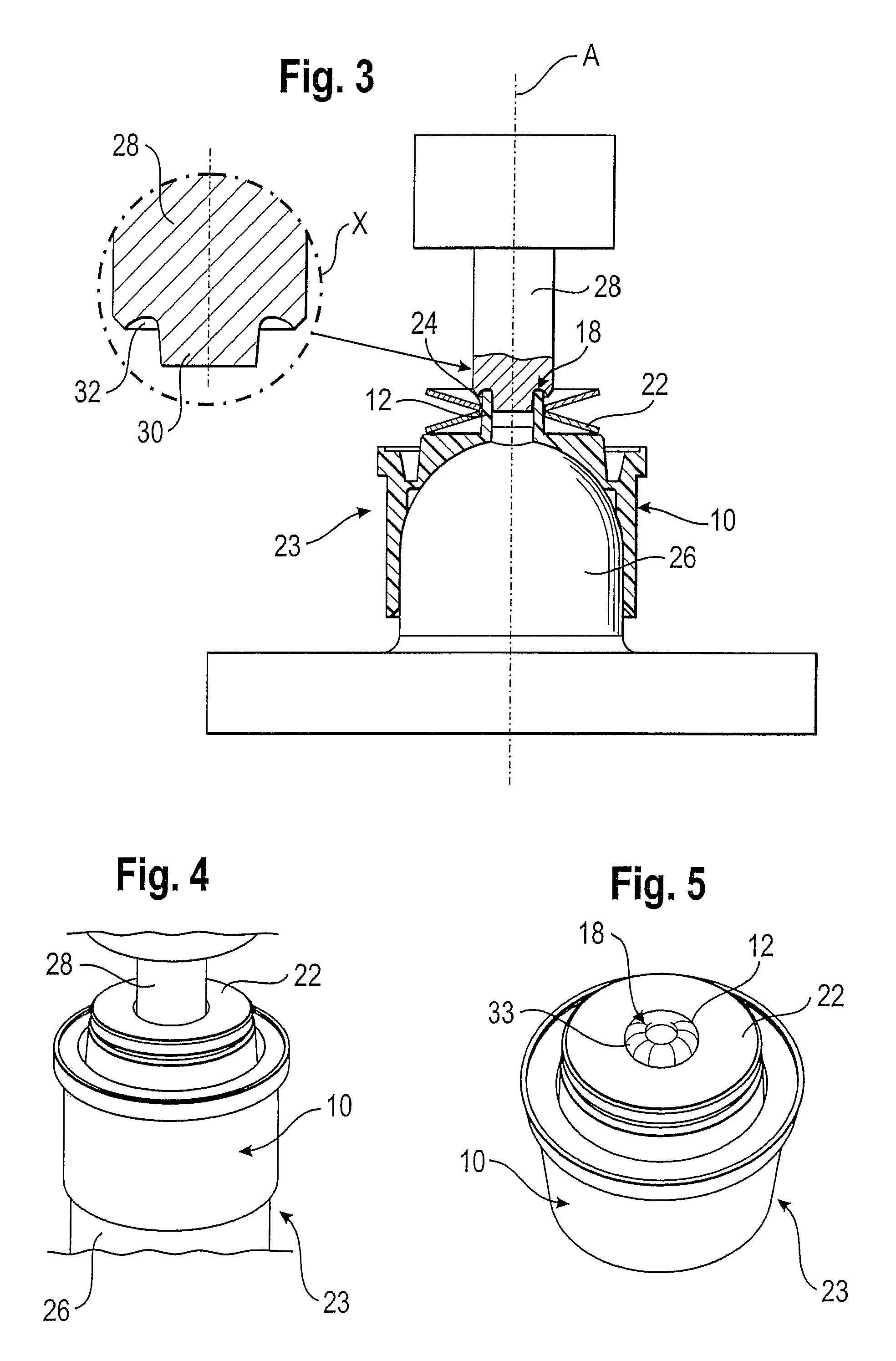
[0028]FIG. 1 shows a known bearing shell 10′ for a ball joint, with a shape which is substantially rotationally symmetrical to a longitudinal axis A′. The bearing shell 10′ has an axial extension 12′, on which latching elements 14′ are formed. The latching elements 14′ can enter into a snap-on connection with a spring element (not shown) in order to fasten the spring element to the bearing shell 10′, so that a pre-mounted bearing shell assembly is produced. According to FIG. 1, the axial extension 12′ is subdivided by notches 16′ into four radially movable latching elements 14′. At a free, axial end 18′ of the extension 12′, each latching element 14′ has a formed-on build-up or undercut, which respectively forms a detent nose 20′ of the associated latching element 14′.

[0029]If a spring element, such as for example a plate spring with a suitable opening, is pressed in the axial direction onto the extension 12′, then the latching elements 14′ deform radially inwards until the plate sp...


PUM

PropertyMeasurementUnit
plastic extensionaaaaaaaaaa
diameteraaaaaaaaaa
radial forcesaaaaaaaaaa

Abstract

A method for manufacturing a bearing shell assembly for a ball joint includes the following steps: a) a bearing shell having a plastic extension is produced; b) a spring element is arranged in a region of the plastic extension; and c) the spring element is fastened to the bearing shell by deformation of the plastic extension. The invention further relates to a bearing shell assembly for a ball joint, including a bearing shell and a spring element, the spring element being non-detachably connected with the bearing shell.

Description

CROSS-REFERENCE TO RELATED APPLICATIONS[0001]This application claims priority to German Patent Application No. 10 2008 003 463.0 filed Jan. 8, 2008, the disclosures of which are incorporated herein by reference in their entirety.BACKGROUND OF THE INVENTION[0002]The invention relates to a bearing shell assembly for a ball joint and a method for manufacturing a bearing shell assembly.[0003]Ball joints are generally known from the prior art and are employed, inter alia, in vehicle construction. For example, they are used as radial ball joints and, in that case, must be able to withstand high radial forces along with low axial forces and large tilting angles. The wear occurring over the lifespan of a radial ball joint can lead to the ball joint causing noises during travel, caused by free play in the joint.[0004]In order to prevent the occurrence of this free play, ball joints already exist in which a pre-stressed spring element is arranged between a joint housing and a bearing shell in...

Claims


Application Information

Patent Timeline
Patent Type & Authority Patents(United States)
IPC IPC(8): B21D53/10B21D53/00B21D39/00B29D33/00
CPCB29C66/5344B29C66/81429F16C11/0685B29C66/80B29C65/08F16C11/08F16C11/0647B29C66/8322F16C11/0633B29C65/607B29C65/568B29L2031/04Y10T29/49668Y10T403/32713F16C2326/01Y10T29/49936Y10T403/32811Y10T29/49636Y10T403/32631Y10T403/32762Y10T29/49908Y10T403/32745B29C65/004B29C66/112B29C66/12441B29C66/12469B29C66/135B29C66/612B29C66/73921F16C11/0638F16C11/0642
Inventor OREND, SVEN-HELGI
Owner THK RHYTHM AUTOMOTIVE GMBH
Learn More