Blade assembly removal from a header of a plant cutting machine

a cutting machine and header technology, applied in the direction of mowers, agriculture tools and machines, etc., can solve the problems of additional vibrations within the header, concentrated weight of the oscillating drive, etc., and achieve the effect of convenient removal or replacement and efficient

Active Publication Date: 2012-04-10
BLUE LEAF I P INC
View PDF22 Cites 114 Cited by
  • Summary
  • Abstract
  • Description
  • Claims
  • Application Information

AI Technical Summary

Benefits of technology

[0007]An advantage of the cutting assembly disclosed herein is that removal of the blade assembly from the head assembly can be efficiently effected by releasing or removing a small number of fasteners, thus allowing an operator to readily remove or replace the blade assembly as needed.

Problems solved by technology

Nevertheless, this header configuration is disadvantaged in that the weight of the oscillating drive is concentrated at the side or end of the header.
Furthermore, relative to a center-mounted oscillating drive, a side- or end-mounted oscillating drive has a tendency to cause additional vibrations within the header during operation.

Method used


Image

  • Blade assembly removal from a header of a plant cutting machine
  • Blade assembly removal from a header of a plant cutting machine
  • Blade assembly removal from a header of a plant cutting machine

Examples


Embodiment Construction

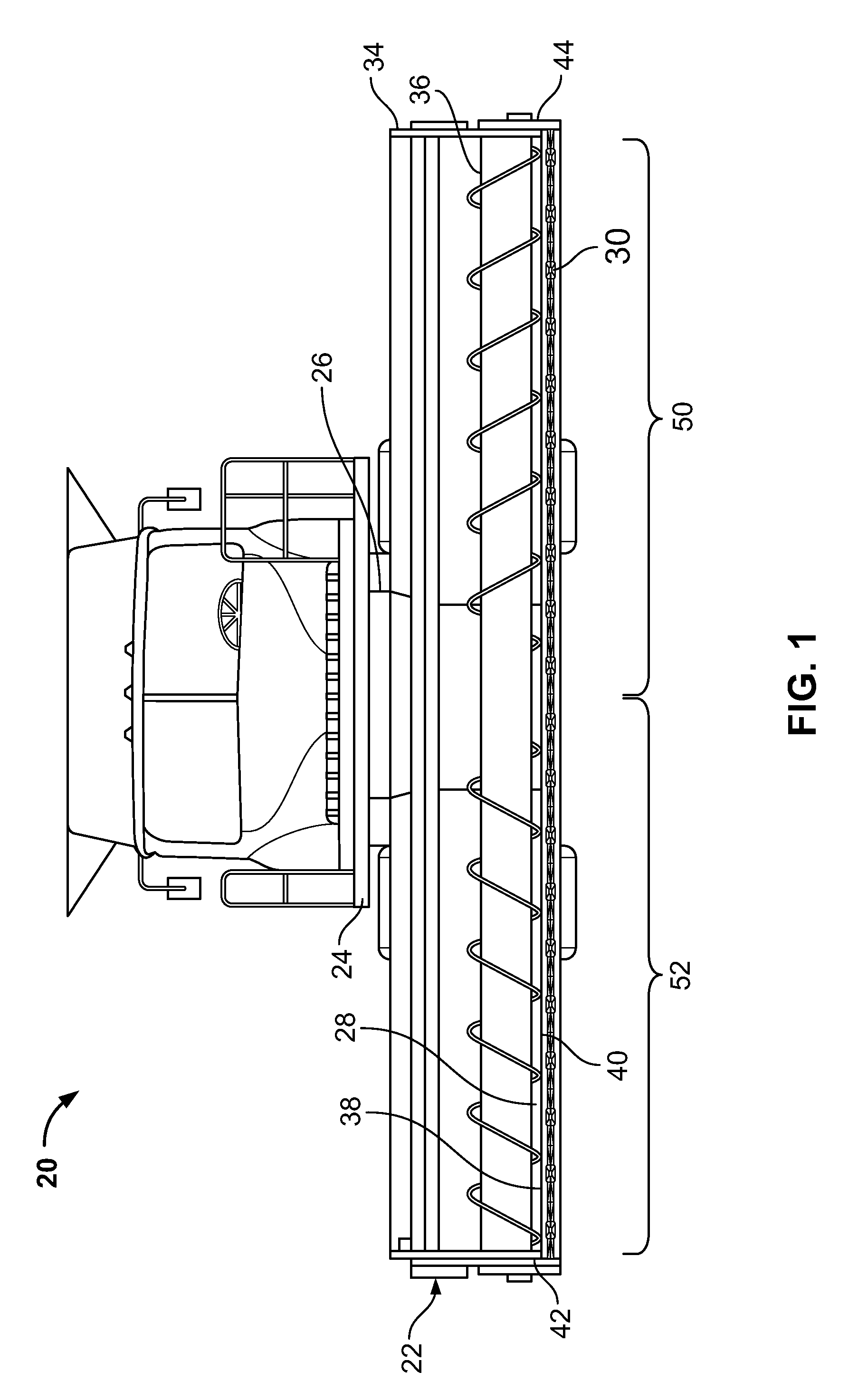
[0023]A combine 20, which is a well-known agricultural cutting machine, is shown in FIG. 1. Combine 20 includes a header 22, which is configured to cut or sever crops, including (without limitation) small grains (e.g., wheat, soybeans), and to induct the cut or severed crops into a feeder 26. Both functions can be performed as combine 20 moves forward over a crop field.

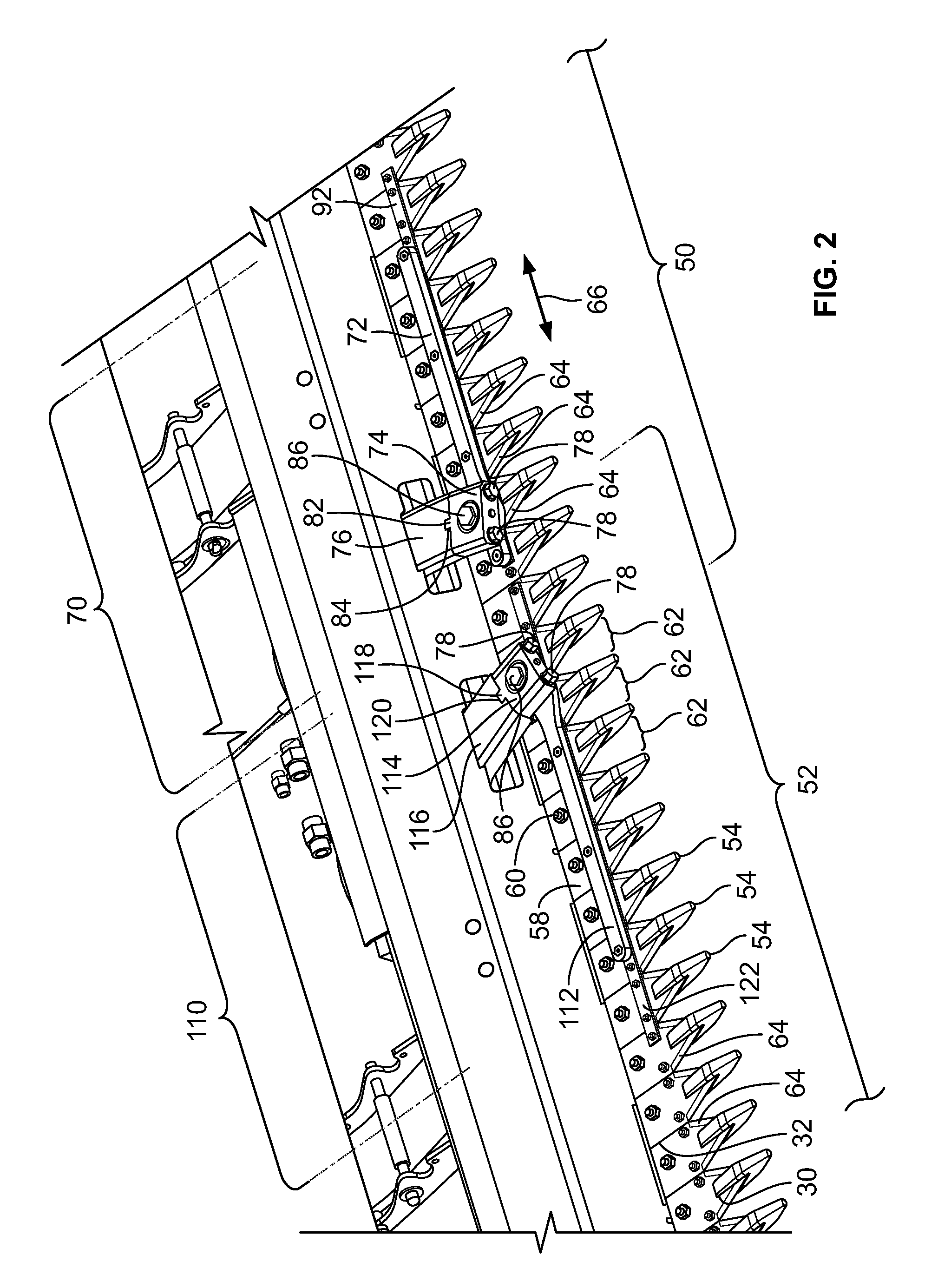
[0024]Header 22 is attached to a forward end 24 of combine 20 and includes a pan or floor 28 that is supported in desired proximity to the surface of a crop field. Header 22 includes an elongate sidewardly extending sickle 30 along a forward edge portion 32 (see FIG. 2) of floor 28. Sickle 30 is configured to cut or sever crops, in preparation for induction into a feeder 26. Additionally, header 22 includes an elongate, sidewardly extending reel 34 disposed above sickle 30. Reel 34 is rotatable in a direction suitable for facilitating the induction of cut or severed crops into feeder 26. Header 22 further includes an ...


PUM


Abstract

A cutting assembly for a header of a plant-cutting machine includes a blade assembly fastened to a head assembly, which is configured to be drivingly connected to a motor. The cutting assembly is suitable for mounting proximate to the center of the header, in an end-to-end relation with another cutting assembly. Removal of the blade assembly from the head assembly can be efficiently effected by releasing or removing a small number of fasteners, thus allowing an operator to readily remove or replace the blade assembly as needed.

Description

[0001]This invention relates generally to a cutting assembly for a header of a plant-cutting machine (e.g., combine, windpower) and, more specifically, to a cutting assembly that is suitable for mounting proximate to the center of the header.BACKGROUND OF THE INVENTION[0002]The cutting assemblies of the known large headers of plant-cutting machines (e.g., combine, windpower) are driven from the side or end of the header by an oscillating drive, which can include, but is not limited to, an eccentric shaft on a rotating hub, a wobble drive, or a similar well-known commercially-available device. A header configuration having an oscillating drive at the side or end of the header is advantageous in that the drive does not obstruct or interfere with the flow of cut plants (e.g., cut crops) into the header. Nevertheless, this header configuration is disadvantaged in that the weight of the oscillating drive is concentrated at the side or end of the header. More specifically, because this we...

Claims


Application Information

Patent Timeline
Patent Type & Authority Patents(United States)
IPC IPC(8): A01D43/00
CPCA01D34/145A01D34/30
Inventor BICH, GARYCARLSON, BEAU A.SCHROEDER, LUKE A.
Owner BLUE LEAF I P INC
Why Eureka
Try Eureka