Automatic-positioning linear guide

a linear guide and automatic positioning technology, applied in the field of linear guides, can solve the problems of increasing the manufacturing cost of the rail, adversely affecting the operation of the linear guide, and aggravating assembly errors and accumulated assembly errors, and achieve the effect of high-precision assembly of the linear guid

Inactive Publication Date: 2012-04-10
TSAI SHU FU
View PDF9 Cites 4 Cited by
  • Summary
  • Abstract
  • Description
  • Claims
  • Application Information

AI Technical Summary

Benefits of technology

[0010]One objective of the present invention is to provide an automatic-positioning linear guide having a driven body combined with two guiding rails settled at two sides of a stationary base, with each roller automatically adjusting a closeness where it is combined with the corresponding guiding rail. In other words, the roller serves to automatically eliminate an assembly error between itself and the corresponding guiding rail and in turn eliminate an accumulated assembly error, thereby achieving a highly precise assembly of the linear guide. It is to be noted that commercially available and ordinary bearings are competent to function as the rollers of the present invention, instead of any component made through special technology or highly precise standards.
[0011]Another objective of the present invention is to provide an automatic-positioning linear guide having a driven body combined with two guiding rails settled at two sides of a stationary base via a plurality of rollers. The driven body adjusts a lateral pressure thereof and in turn changes lateral pressures that a plurality of rollers applies to the guiding rails to automatically eliminate assembly errors and an accumulated assembly error between the rollers and the guiding rails, so that the rollers and the guiding rails can be assembled with proper closeness.
[0012]Another objective of the present invention is to provide an automatic-positioning linear guide, which facilitates preventing deformation of a driven body, ensuring stable movement of the driven body, protecting rollers and guiding rails from bearing an excessive lateral pressure, averting undue attrition of the rollers and the guiding members, and lengthening service lives of the rollers and the guiding rails.
[0013]Another objective of the present invention is to provide an automatic-positioning linear guide, which can be configured so that the linear guide has an arbitrary linear length. Thus, preparation as well as assembly of the linear guide are convenient, and linear precision as well as smooth movement are ensured.

Problems solved by technology

Such high accurateness can significantly raise the manufacturing costs of the rail 10 and the rollers 16.
However, even if the rail 10 and the rollers 16 are formed with the anticipated accurateness, when both are later combined together, assembly errors happening therebetween cannot be fully averted, and such assembly errors can accumulate and cause an accumulated assembly error that adversely effect the operation of the linear guide.
Consequently, after a period of use, the assembly errors and accumulated assembly error can become aggravated, and the driven body 15 will be subject to undesirable jolts during its linear movement.
Besides, since the rollers and rail 10 are assembled relying on manual operation without objective adjustment reference, in the event that the rollers 16 and the rail 10 are combined with undue closeness, the friction therebetween is increased and adversely affects the smooth linear movement of the driven body 15.
Besides, the undue friction can significantly reduce the service lives of the rollers 16 and the rail 10.

Method used


Image

  • Automatic-positioning linear guide
  • Automatic-positioning linear guide
  • Automatic-positioning linear guide

Examples


Embodiment Construction

[0032]While a preferred embodiment is provided herein for illustrating the concept of the present invention as described above, it is to be understood that the extent of deformation or displacement of the components in these drawings are made for better explanation and need not to be made in scale.

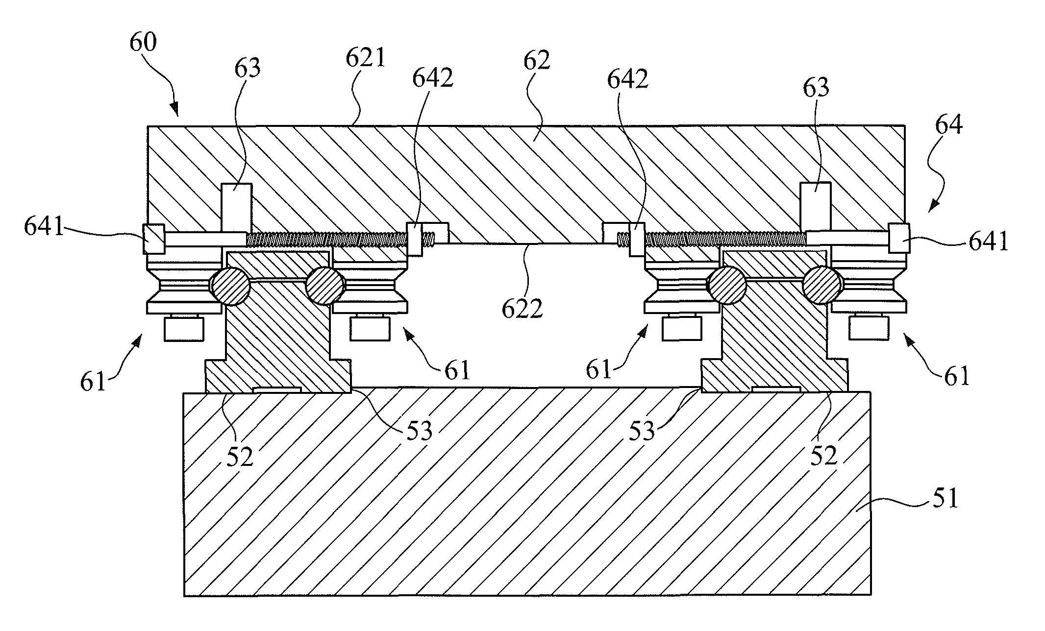
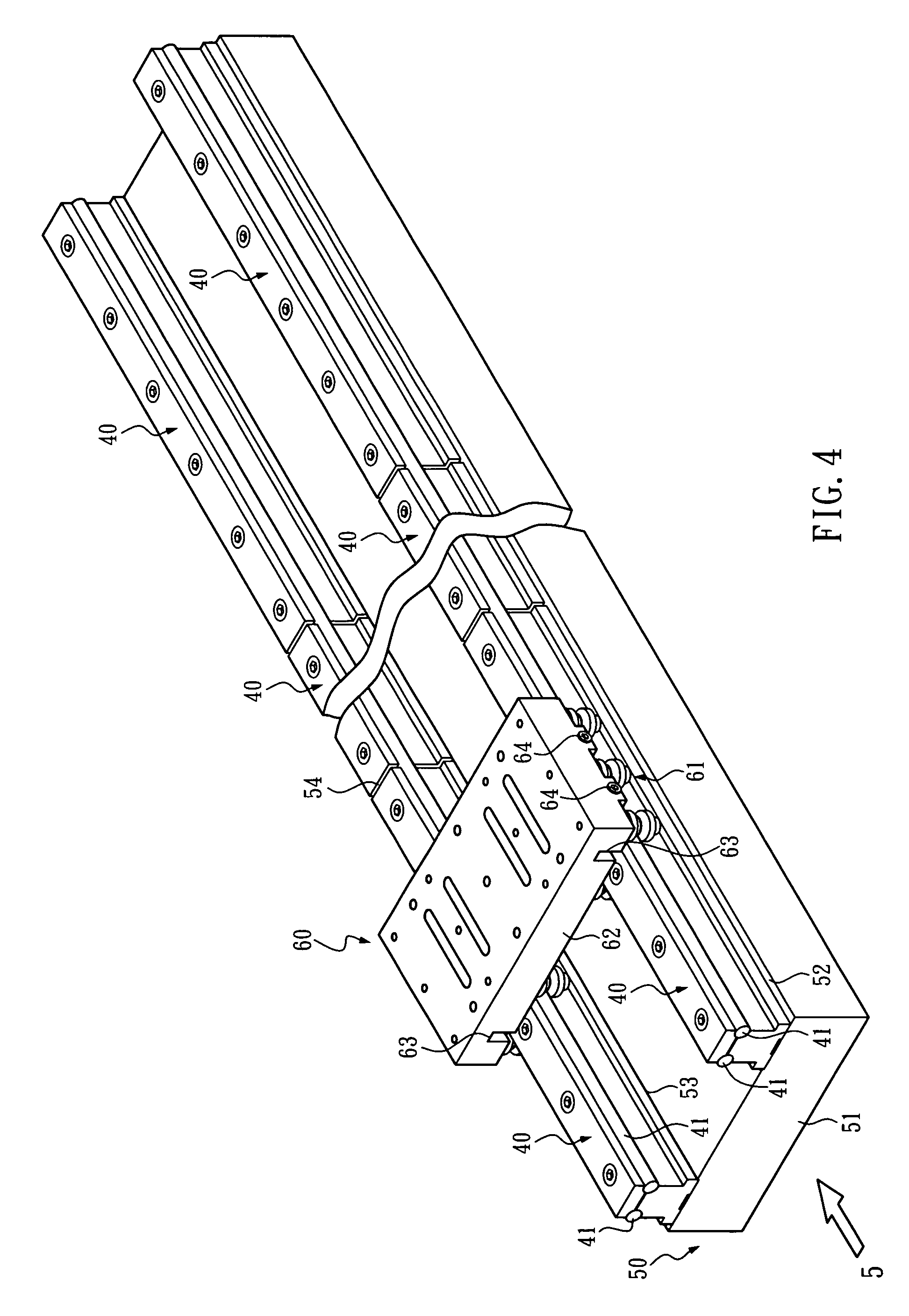
[0033]As shown in FIGS. 4 and 5, the linear guide of the present invention comprises a stationary base 50 and a driven body 60. A pair of guiding rail sets 40 are provided at two sides of a top surface of the stationary base 50. The guiding rail set 40 at each side has a pair of guiding rails 41 settled abreast. At least one pair of rollers 61 are provided at two sides of a bottom surface of the driven body 60. The driven body 60 is mounted on the stationary base 50 so that each said roller 61 contacts an outer surface of the corresponding guiding rail 41.

[0034]In FIGS. 6, 7 and 8, the stationary base 50 of the present invention comprises a base 51. A pair of fixing portions 52 are provide...


PUM


Abstract

An automatic-positioning linear guide has a driven body combined with guiding rails at two sides of a stationary base via a plurality of rollers. Each of the rollers is composed of two bearings combined by an axial shaft and can be assembled with the corresponding guiding rail without an assembly error therebetween.

Description

BACKGROUND OF THE INVENTION[0001]1. Technical Field[0002]The present invention relates to linear guides and, more particularly, to a linear guide having functions of automatic positioning, automatic assembly-error eliminating, and automatic accumulated-error eliminating.[0003]2. Description of Related Art[0004]A conventional roller linear guide, as shown in FIGS. 1, 2 and 3, primarily comprises a rail 10 and a driven body 15 that can move back and forth along the rail 10. Two sides of the driven body 15 are combined with two sides of the rail 10 through a plurality of rollers 16, which assist the driven body 15 in its linear movement with reduced friction as well as reduced noise and which smoothes the linear movement of the driven body 15.[0005]Each of the rollers 16 of the driven body 15 has an integral outer bush 161 where an outer annular groove 162 is formed for receiving a corresponding side of the rail 10.[0006]People who have ordinary skill in the art of linear guides would ...

Claims


Application Information

Patent Timeline
Patent Type & Authority Patents(United States)
IPC IPC(8): F16C19/00
CPCF16C29/045
Inventor TSAI, SHU-FU
Owner TSAI SHU FU
Why Eureka
Try Eureka