Connector having protection components

a technology of protection components and connectors, applied in the direction of coupling device connections, coupling protective earth/shielding arrangements, two-part coupling devices, etc., can solve the problems of inability to anticipate the value of the generated high-voltage surge, the burn down of the integrated circuit (ic), and the failure and the ability of the connector to protect against static electricity and lightening can be increased. , the effect of low allowan

Inactive Publication Date: 2012-04-10
CHANG NAI CHIEN
View PDF21 Cites 10 Cited by
  • Summary
  • Abstract
  • Description
  • Claims
  • Application Information

AI Technical Summary

Benefits of technology

[0008]The present invention is to provide a connector having protection components. The protection components are electrically connected between lines as well as the lines and a grounding line, thereby increasing the capability of the connector for withstanding the high-voltage surge generated by static electricity or lightening.
[0010]In comparison with prior art, the present invention has advantageous features as follows. A gas discharge tube, a transient voltage suppressor, and a transformer are used as surge protection components for protection between the lines as well as the lines and a grounding line. In this way, the capability of the connector for protecting against static electricity and lightening can be increased. Further, since the gas discharge tube has a low allowance, a smaller signal distortion, easy assembly and low cost, using the gas discharge tube as a protection component increases the performance and efficiency of the connector.

Problems solved by technology

Thus, when a high voltage is generated in the external cable due to static electricity or lightening, the high voltage will be conducted to the network connector of the computer by the external cable, which makes the mother board electrically connected to the network connector to burn down.
Thus, the value of the generated high-voltage surge cannot be expected.
As a result, the generated voltage is still larger than the working voltage of the integrated circuit (IC) inside the connector, so that the integrated circuit (IC) may burn down.

Method used


Image

  • Connector having protection components
  • Connector having protection components
  • Connector having protection components

Examples


Embodiment Construction

[0020]In order to better understand the features and technical contents of the present invention, a detailed description relating thereto will be made with reference to the accompanying drawings. It is noteworthy to point out that the drawings is provided for the illustration purpose only, but not intended for limiting the scope of the present invention.

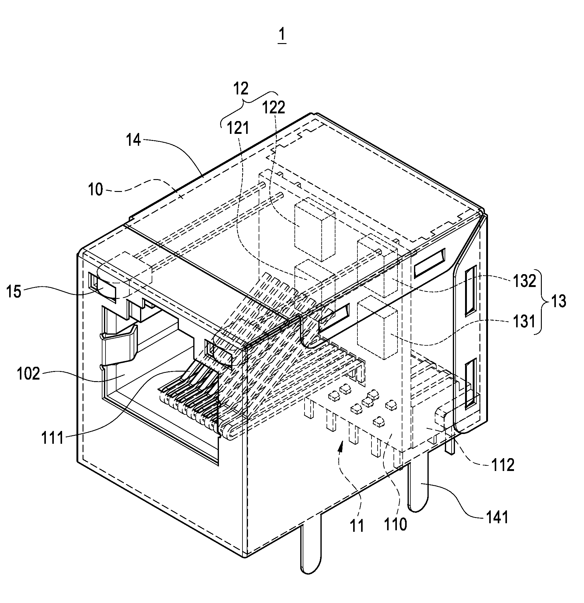
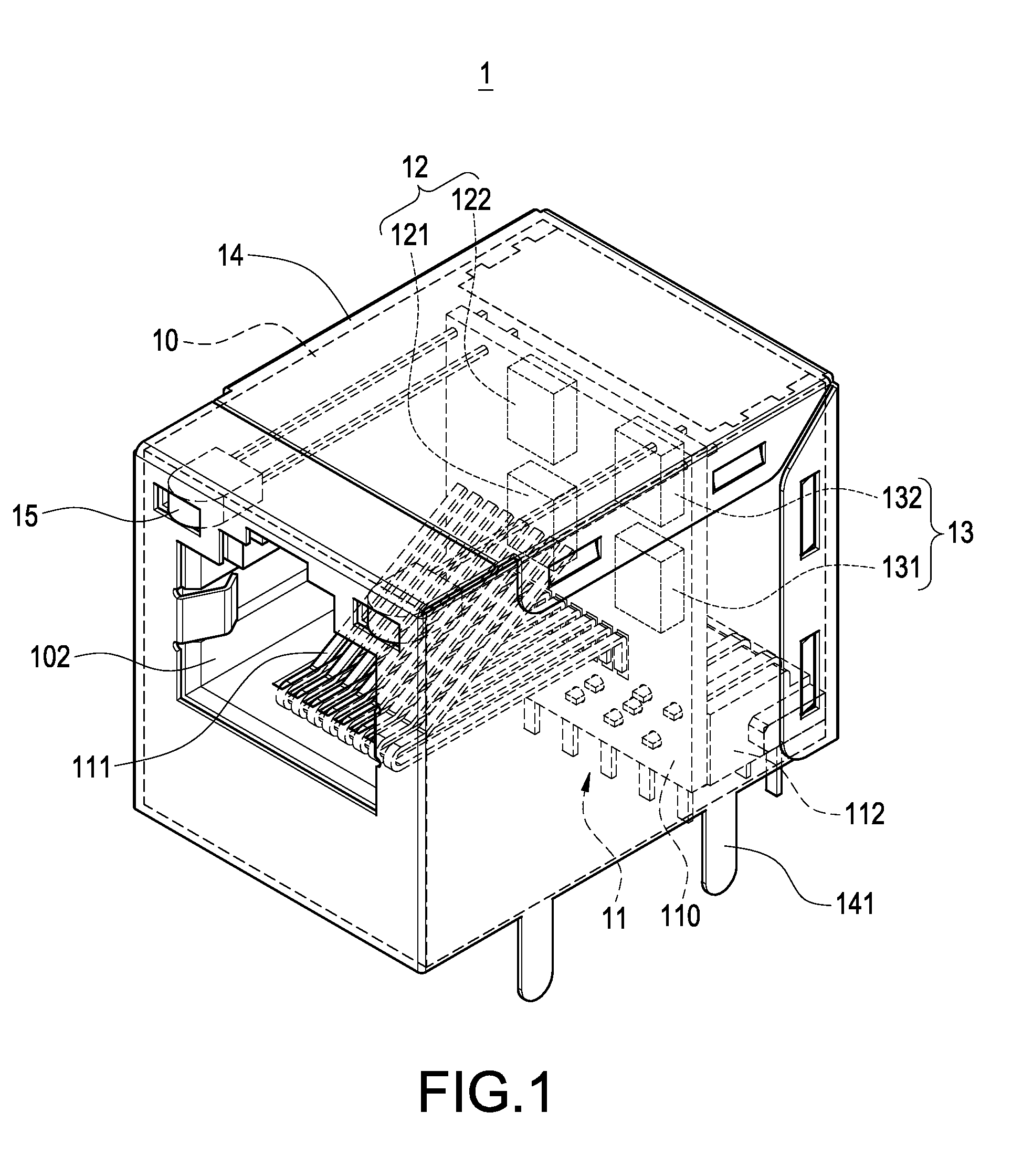
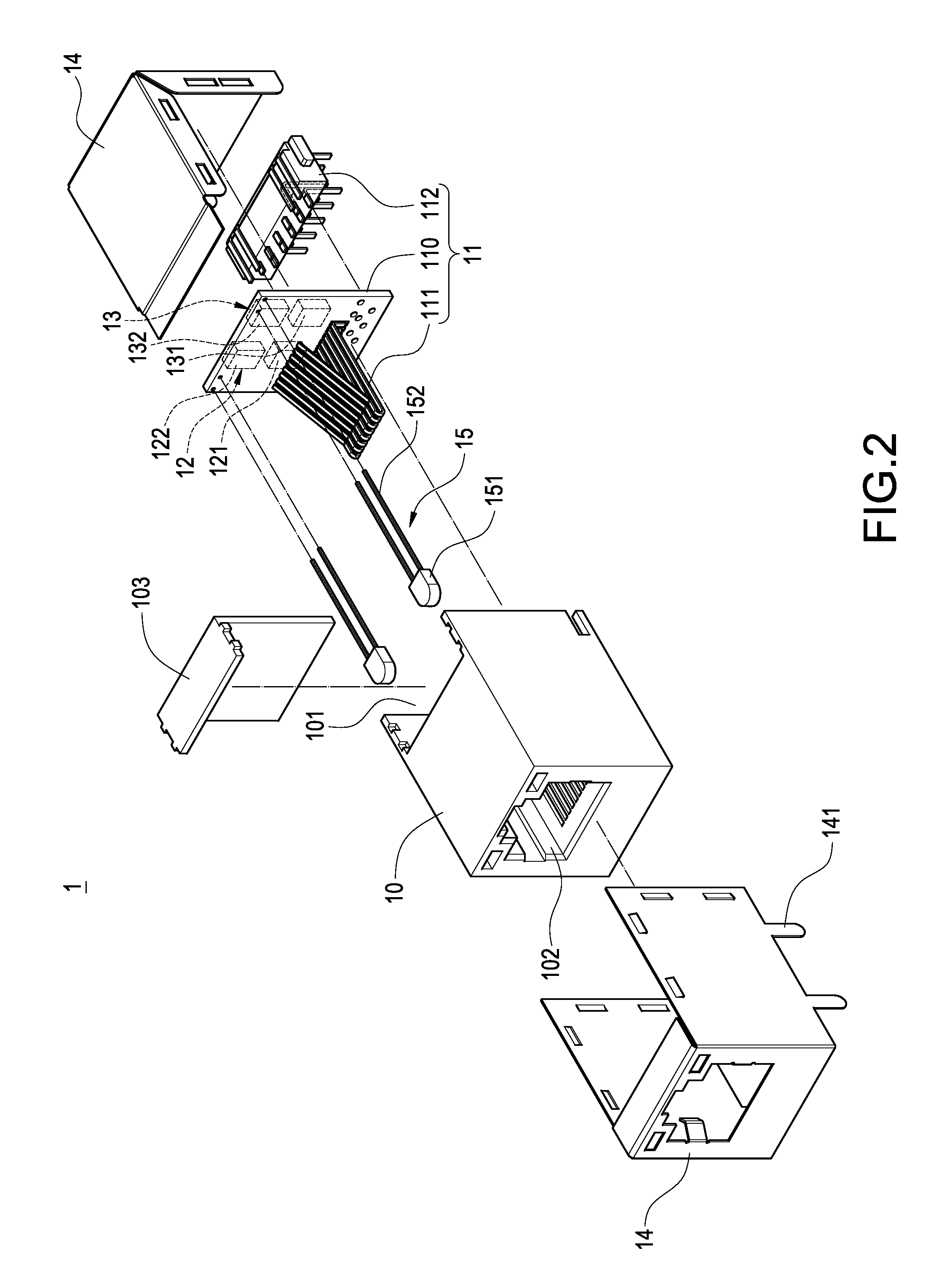
[0021]Please refer to FIGS. 1 and 2. FIG. 1 is a perspective view showing the external appearance of a preferred embodiment of the present invention. FIG. 2 is an exploded perspective view showing a preferred embodiment of the present invention. The present invention provides a connector 1, which includes an insulation body 10, a signal transmission module 11, a first protection component set 12, a second protection component set 13, and a metallic casing 14 covering the above-mentioned components.

[0022]The interior of the insulation body 10 has an accommodating space 101 for accommodating the signal transmission module 11, the first...


PUM


Abstract

A connector having protection components includes an insulation body, a signal transmission module provided in the insulation body, a first protection component set and a second protection component set both electrically connected to the signal transmission module. The signal transmission module includes a circuit board and an input terminal set and an output terminal set electrically connected to the circuit board. The first protection component set is electrically connected between the input terminal set and the output terminal set for protection between the lines. The second protection component set is electrically connected between the first protection component set and a grounding line, thereby providing protection between the lines and a grounding line.

Description

BACKGROUND OF THE INVENTION[0001]1. Field of the Invention[0002]The present invention relates to a connector, and in particular to a connector in which a plurality of protection components is provided.[0003]2. Description of Prior Art[0004]With the advancement of science and technology as well as the rapid development of semiconductor industry, computer has become a necessary electronic product in our daily life. Recently, owing to the rapid development of Internet, a user can use one computer to access the Internet for browsing data and communicating with other users in the Internet.[0005]In addition to novel wireless network technology, a mother board of the modern computer is provided with a network connector, such as RJ-45 connector. The network connector is electrically connected to an external cable, thereby connecting the computer to the Internet.[0006]However, the above-mentioned external cable such as the network line or an optical fiber cable, is usually provided outside a...

Claims


Application Information

Patent Timeline
Patent Type & Authority Patents(United States)
IPC IPC(8): H01R13/648
CPCH01R13/6658H01R24/64H01R27/02H01R13/6633H01R13/6666
Inventor CHANG, NAI-CHIEN
Owner CHANG NAI CHIEN
Why Eureka
Try Eureka