Wheel and brake assembly

a technology of brake assembly and wheel, which is applied in the direction of braking elements, structural/machine measurement, instruments, etc., can solve the problems of increasing the weight of the wheel and brake assembly, excessive torque bar deflection, etc., and achieves the effect of reducing or substantially eliminating excessive vibration-inducing deflection, improving the dynamic stability of the torque bar, and resilient compressibility

Active Publication Date: 2012-04-17
THE BF GOODRICH CO
View PDF11 Cites 18 Cited by
  • Summary
  • Abstract
  • Description
  • Claims
  • Application Information

AI Technical Summary

Benefits of technology

[0005]The present invention provides a method and device for supporting torque bars used in a wheel and brake assembly to improve the dynamic stability of the torque bars with at most only a minor thermal penalty. The method and device reduces or substantially eliminates excessive vibration-induce deflections. In a preferred embodiment, a spacer block is interposed between the wheel and torque bar at a mid-span location along the torque bar. The spacer block, which preferably is made of an insulating material that may have some resilient compressibility, is compressed between the torque bar and wheel well. This provides effective resistance to radial vibration while frictional and / or mechanical interference between the spacer block and both the torque bar and wheel well resists tangential deflection of the torque bar during braking. As will be appreciated, the method and device of the present invention can easily be applied to retrofit existing wheel and brake assemblies to improve the operating characteristics of the torque bars and / or allow for the use of lighter and / or smaller torque bars.
[0008]In accordance with yet another aspect of the invention, a wheel and brake assembly comprises a wheel including a wheel well, the wheel well being generally cylindrical and coaxial with a rotational axis of the wheel, and a torque bar connected to the wheel. A radially outer spacer block is secured to the wheel against circumferential movement and a radially inner spacer block is secured to the torque bar against movement transverse to the torque bar. The radially outer spacer block and radially inner spacer block are engaged with each other and movable with respect to each other at an interface therebetween. Friction between the radially outer spacer block member and the radially inner spacer block member damps movement of the torque bar.

Problems solved by technology

Torque bars of the type just described are susceptible to vibration which can result in excessive torque bar deflection both radially and tangentially relative to the wheel.
This undesirably increases the weight of the wheel and brake assembly, which is particularly undesirable in aircraft.

Method used


Image

  • Wheel and brake assembly
  • Wheel and brake assembly
  • Wheel and brake assembly

Examples


Embodiment Construction

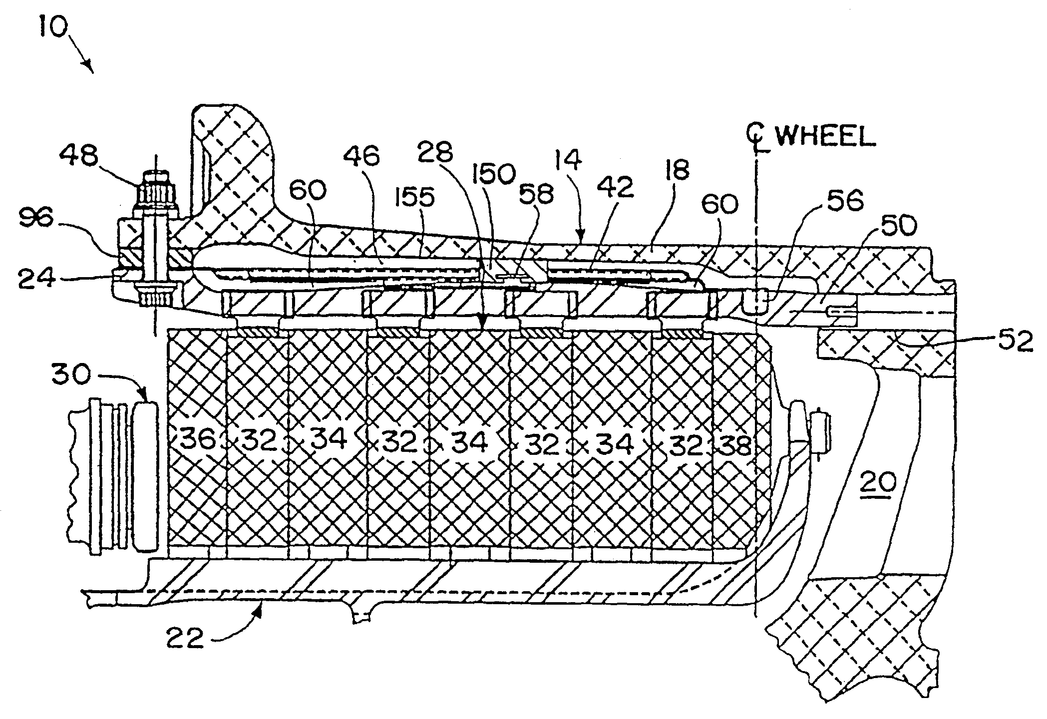
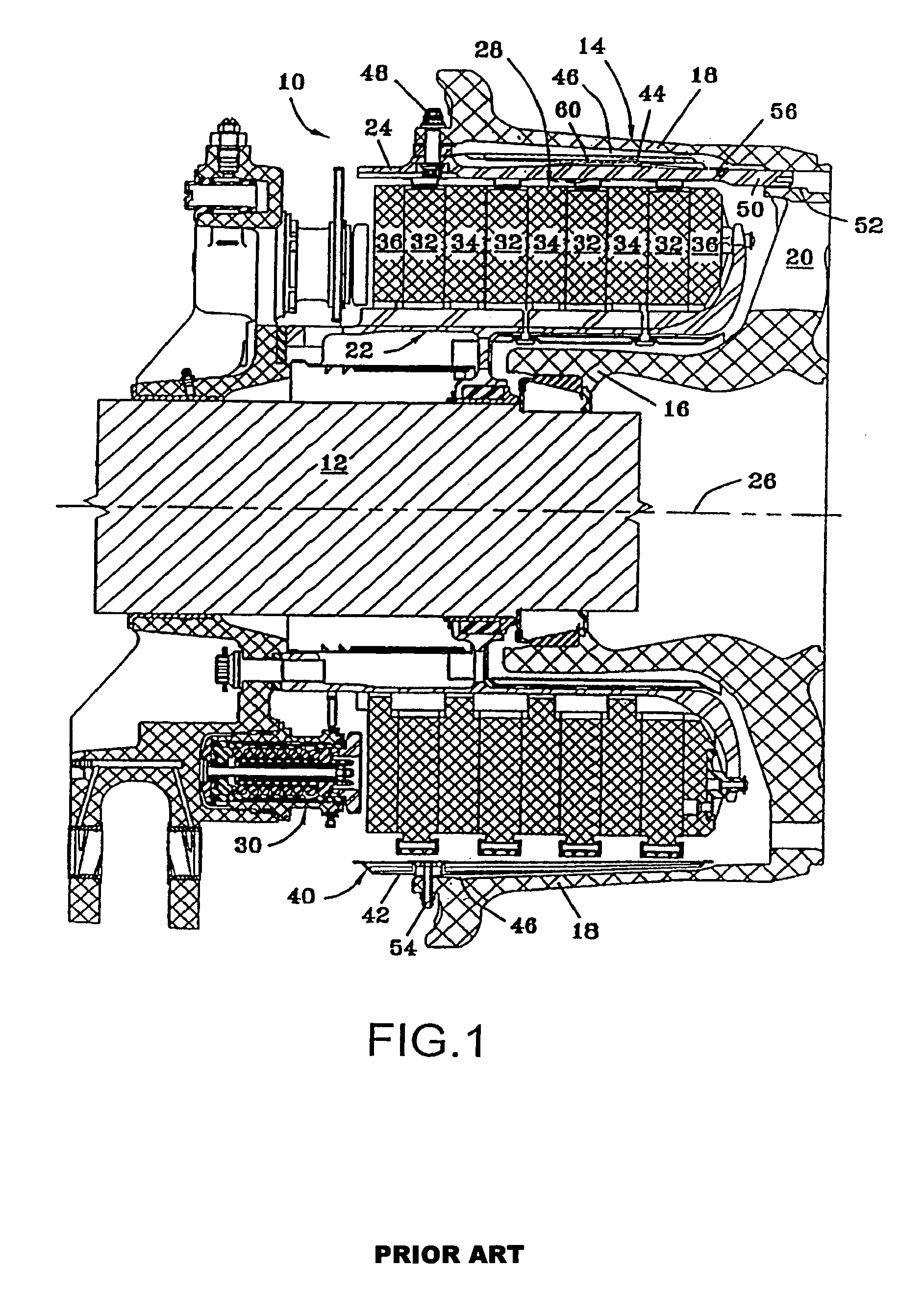
[0029]Referring now to the drawings in detail and initially to FIGS. 1-5, an exemplary wheel and brake assembly is indicated generally by reference numeral 10. The wheel and brake assembly shown in FIGS. 1-5C is fully described in commonly assigned U.S. Pat. No. 7,051,845 which is hereby incorporated herein by reference in its entirety.

[0030]In FIG. 1, the aircraft wheel and brake assembly 10 is shown mounted on an aircraft bogie axle 12. The wheel and brake assembly 10 comprises a wheel 14 (only the inboard half of the wheel is shown in FIG. 1) having a hub 16 and a wheel well 18 concentric with the hub 16, and a web 20 interconnecting the hub 16 and the wheel well 18. A torque take-out assembly 22 is aligned with the hub 16, and the wheel 14 is rotatable relative to the torque take-out assembly 22.

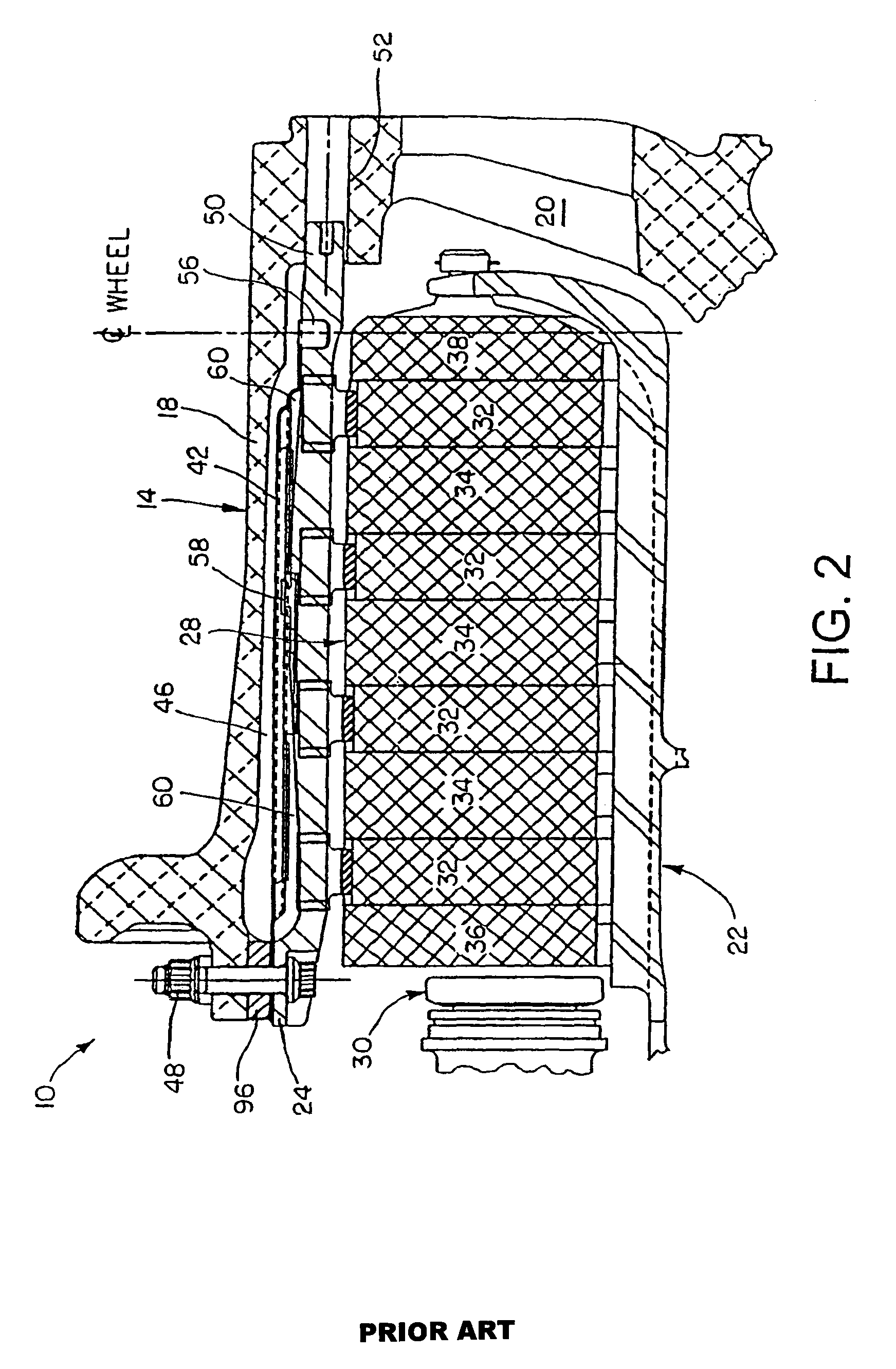
[0031]As shown in FIG. 2, a plurality of torque bars 24 are fixed to the wheel 14 generally parallel to the axis of rotation 26 of the wheel and spaced from the wheel well 18. A heat sin...


PUM


Abstract

A wheel and brake assembly (10) having a torque bar (24) supported at a mid-span location. The torque bar (24) can be pre-loaded at a mid-span location. The pre-load can be effected by a spacer block (150) that is interposed between the wheel well and the torque bar (24). The method and device of the present invention can be used with existing wheel and brake assemblies. The spacer block can be a two-part spacer block.

Description

RELATED APPLICATIONS[0001]This application is a national phase of International Application No. PCT / US2007 / 066413, filed Apr. 11, 2008, published in English as WO 2007 / 118254, which claims the benefit of U.S. Provisional Application No. 60 / 744,644 filed Apr. 11, 2006, which are hereby incorporated herein by reference.FIELD OF THE INVENTION[0002]The present invention relates generally to aircraft wheel and brake assemblies. More particularly, the invention relates to torque transmitting drive bars fastened to the radially inner surface of a wheel well of an aircraft wheel for engagement with brake rotors.BACKGROUND OF THE INVENTION[0003]Torque bars, also known as torque transmitting drive lugs, are employed in aircraft wheel and brake assemblies to couple the wheels to the rotors of the brake assembly. The torque bars typically extend parallel to the wheel axis and have an outboard end inserted in an aperture formed in the web of the wheel and an inboard end attached to a radially in...

Claims


Application Information

Patent Timeline
Patent Type & Authority Patents(United States)
IPC IPC(8): F16D55/36F16D65/28G01M99/00
CPCF16D55/36F16D65/78F16D2065/1368F16D2065/1392F16D2065/785
Inventor ENRIGHT, JOHN J.MILLER, JERRY L.HOUSER, JOSHUA C.
Owner THE BF GOODRICH CO
Why Eureka
Try Eureka