Computer interface apparatus including linkage having flex

a computer interface and linkage technology, applied in the field of interface devices, can solve the problems of not providing not being able to experience an entire sensory dimension in virtual reality simulations, and unable to provide force feedback to a user, etc., to achieve high-reality force feedback, low cost, and low cost

Inactive Publication Date: 2010-10-26
IMMERSION CORPORATION
View PDF303 Cites 20 Cited by
  • Summary
  • Abstract
  • Description
  • Claims
  • Application Information

AI Technical Summary

Benefits of technology

[0013]The present invention provides a human/computer interface apparatus and method which can provide from one to six degrees of freedom to a user-manipulable object and low cost, highly realistic force feedback to the user of the apparatus. The structure of the apparatus permits transducers to be positioned such that thei

Problems solved by technology

However, 2-dimensional input devices tend to be awkward and inadequate to the task of interfacing with 3-dimensional virtual reality simulations.
The Immersion PROBE, however, does not provide force feedback to a user and thus does not allow a user to experience an entire sensory dimension in virtual reality simulations.
Since actuators which supply force feedback tend to be heavier and larger than sensors, they would provide inertial constraints if added to a device such as the Immersion PROBE.
There is also the problem of coupled actuators.
While it is possible to ground all of the actuators in a serial chain by using a complex transmission of cables or belts, the end result is a low stiffness, high friction, high damping transmission which corrupts the bandwidth of the system,

Method used


Image

  • Computer interface apparatus including linkage having flex
  • Computer interface apparatus including linkage having flex
  • Computer interface apparatus including linkage having flex

Examples


embodiment 14

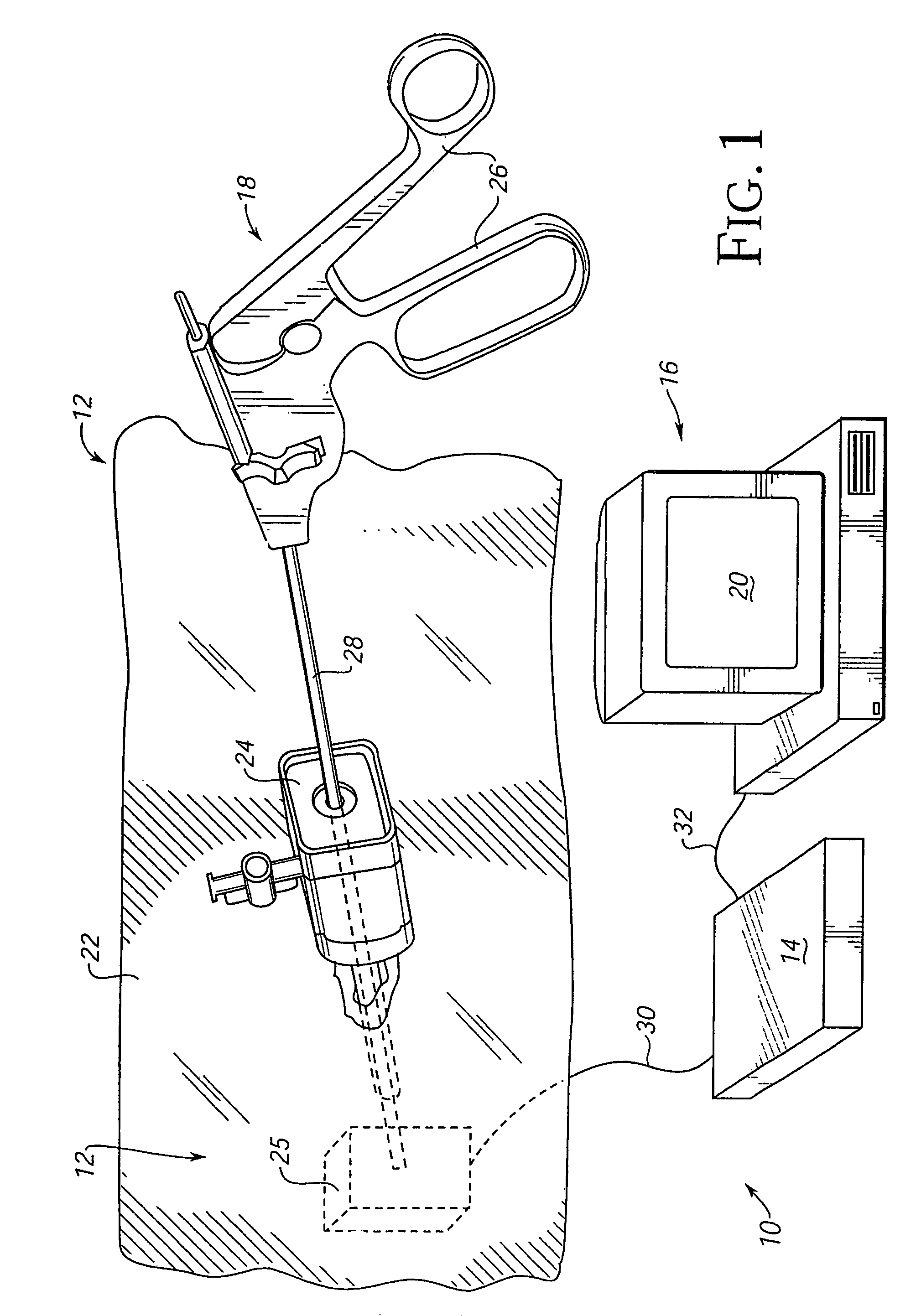
[0064]The electronic interface 14 is a component of the human / computer interface apparatus 12 and may couple the apparatus 12 to the host computer 16. Electronic interface 14 can be included within a housing of mechanical apparatus 25 or be provided as a separate unit, as shown in FIG. 1. More particularly, interface 14 is used in preferred embodiments to couple the various actuators and sensors of apparatus 25 (described in detail below) to computer 16. One suitable embodiment of interface 14 is described in detail with reference to FIG. 9, in which the interface can include a dedicated interface card to be plugged into computer 16. A different embodiment 14′ of interface 14 is described in detail with respect to FIG. 20, in which the interface includes a microprocessor local to the apparatus 12 and can be coupled to computer 16 through a slower, serial interface or a parallel interface.

[0065]The electronic interface 14 can be coupled to mechanical apparatus 25 of the apparatus 12 ...

embodiment 300

[0180]FIGS. 22d and 22e show an alternate embodiment 300′ of the interface apparatus 300 shown in FIGS. 22a and 22b. Interface apparatus 300′ provides two linear degrees of freedom to object 44 so that the user can translate object 44 along the X axis, along the Y axis, or along both axes (diagonal movement). Apparatus 300′ includes a circuit board 308 that includes voice coil actuators 310a and 310b and guides 318. These components operate substantially similar to the equivalent components in apparatus 300.

[0181]A main difference between the embodiments of FIGS. 22a-b and FIGS. 22d-e is that object 44 is rigidly coupled to circuit board 308. Thus, when circuit board 308 is translated along axis X and / or axis Y, shown by arrows 320a and 320b, object 44 is translated in the same directions, as shown by arrows 350 and 352, respectively, providing the object with linear degrees of freedom. Thus, both user object 44 and circuit board 308 move in linear degrees of freedom. This is unlike...

third embodiment

[0188]FIG. 23c is a detailed view of the rollers and drive bar of the friction drive 360. Drive bar 366 is preferably round or square wire that is flexible in at least one direction. Two passive rollers 376a and 376b can be coupled together and to drive roller 374 by non-tensile connections 380. The flexibility in drive bar 366 allows the drive bar to bend around the rollers and creates a higher friction, thus preventing slippage of the drive bar.


PUM


Abstract

A method and apparatus for interfacing the motion of a user-manipulable object with an electrical or computer system includes a user object physically contacted by a user. A gimbal mechanism is coupled to the user object, such as a joystick or a medical tool, and provides at least two degrees of freedom to the user object. The gimbal mechanism preferably includes multiple members, at least two of which are formed as a unitary member which provides flex between the selected members. An actuator applies a force along a degree of freedom to the user object in response to electrical signals produced by the computer system. A sensor detects a position of the user object along the degree of freedom and outputs sensor signals to the computer system. Another embodiment includes a host computer system and a local microprocessor, separate from the host computer, for communicating with the host computer and controlling the forces output by the actuators according to a processor subroutine selected in accordance with a host command, sensor signals, and timing information. Another embodiment of the interface apparatus uses voice coil actuators that produce forces in either linear or rotary degrees of freedom using currents applied in a magnetic fields. A friction drive mechanism of the present invention can be coupled between an actuator and a gimbal mechanism. Force from the actuator is transmitted to the gimbal mechanism through frictional contact of members of the friction drive mechanism.

Description

CROSS REFERENCE TO RELATED APPLICATIONS[0001]This application is a continuation of U.S. patent application Ser. No. 09 / 748,051, filed on Dec. 22, 2000 now U.S. Pat. No. 6,697,048, on behalf of Louis B. Rosenberg et al., entitled, “Computer Interface Apparatus Including Linkage Having Flex,” which is a continuation of U.S. patent application Ser. No. 09 / 140,717, filed on Aug. 26, 1998, now U.S. Pat. No. 6,201,533, on behalf of Louis B. Rosenberg et al., entitled “Method and Apparatus For Applying Force in Force Feedback Devices Using Friction,” which is a divisional of U.S. patent application Ser. No. 08 / 560,091 filed on Nov. 17, 1995, now U.S. Pat. No. 5,805,140, on behalf of Louis B. Rosenberg et al., entitled “High Bandwidth Force Feedback Interface Using Voice Coils and Flexures,” which is a continuation-in-part of U.S. patent application Ser. No. 08 / 374,288 filed on Jan. 18, 1995, now U.S. Pat. No. 5,731,804, on behalf of Louis B. Rosenberg et al., entitled “Method and Apparatus...

Claims


Application Information

Patent Timeline
IPC IPC(8): G09G5/08G06F3/033G05G11/00A61B19/00B25J9/16G01B5/008G01B7/004G01B21/04G05B19/42G05D25/02G05G9/047G06F3/00G06F3/01G06F3/038G09B9/28G09B23/28
CPCB25J9/1692G01B5/008G01B7/004G01B21/04G05B19/4207G05D25/02G05G9/047G06F3/016G06F3/0346G06F3/038G06F3/0383G09B9/28G09B23/28G09B23/285A61B19/26A63F2300/1037G05G9/04737G05G2009/0474G05G2009/04759G05G2009/04766G06F2203/015H01H2003/008A61B90/50
Inventor ROSENBERG, LOUIS B.SCHENA, BRUCE M.
Owner IMMERSION CORPORATION
Why Eureka
Try Eureka