
Tiled structures and brackets therefor

a technology of tiled structures and brackets, which is applied in the direction of walls, coverings/linings, constructions, etc., can solve the problems of water infiltration into the wall, substantial risk of breakage or damage to tile veneers, and damage to the structure of substrates

Active Publication Date: 2012-04-24
SCALISE DAVID H
View PDF21 Cites 6 Cited by
  • Summary
  • Abstract
  • Description
  • Claims
  • Application Information

AI Technical Summary

Benefits of technology

[0008]The present invention seeks to address the above-described needs of the tile industry, to overcome the disadvantages of current installation techniques used in the industry, and to enable expanded uses of tile in new applications not previously considered feasible. Basically, the present invention proposes the use of a novel form of support bracket by which tile may be installed with or without a traditional form of substrate. In various embodiments, the bracket of the present invention is particularly adapted for use in traditional tile applications to enable the mounting and support of accessories, such as to a vertical tiled wall structure, without requiring fasteners which must penetrate the wall structure.
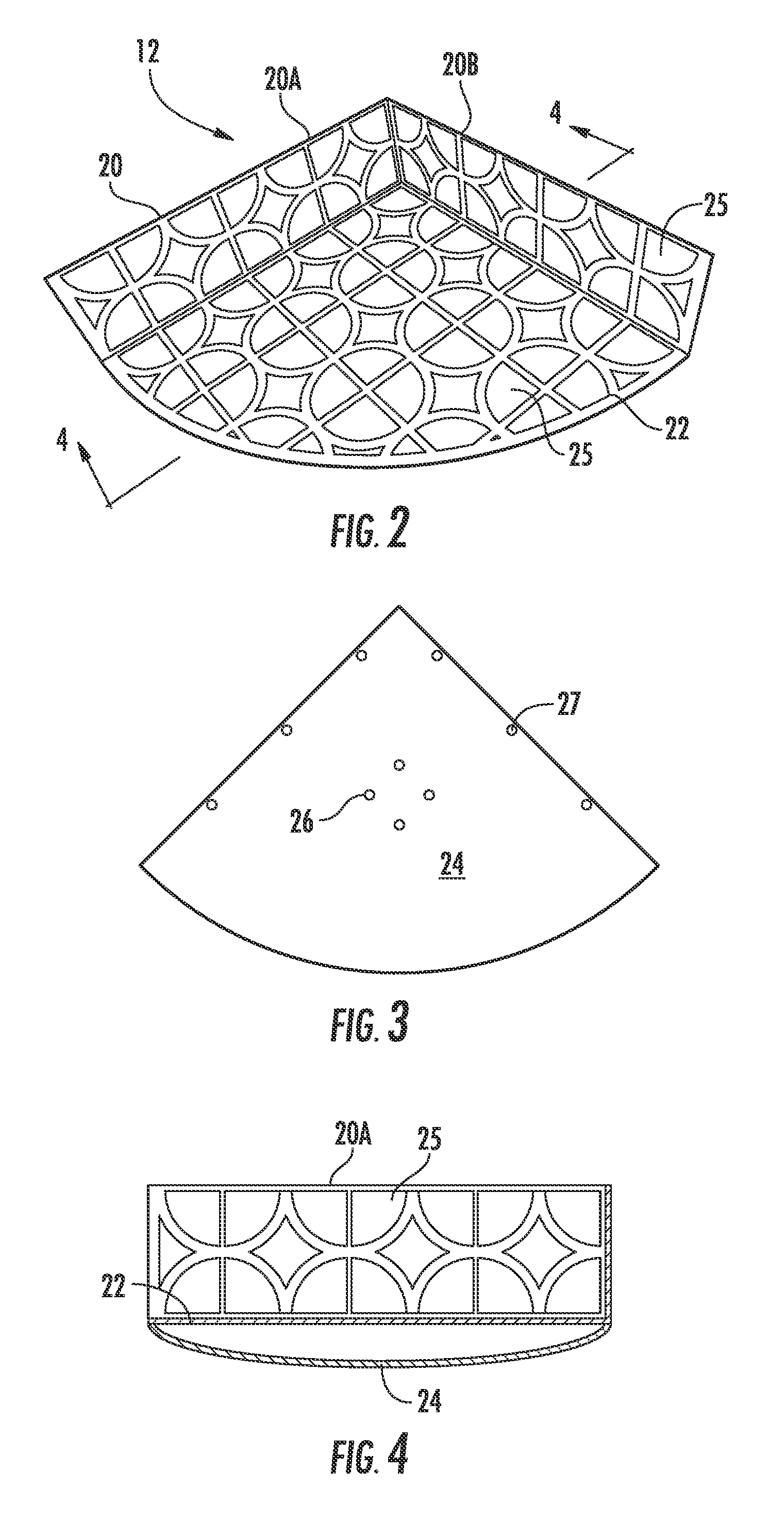
[0010]Various embodiments of the bracket and various embodiments of tile structures incorporating such brackets are contemplated. In accordance with one embodiment of the invention, the present bracket comprises a base mounting portion and a support portion rigidly affixed to the base mounting portion and projecting outwardly therefrom. The base mounting portion has a plurality of perforations therethrough for embedding of the base mounting portion in the adhesive mortar of a tile structure in abutting relation to a substrate to secure the base mounting portion thereto, with the mortar flowing through the perforations to substantially cover opposite sides of the base mounting portion for also adhering the tile veneer over the base mounting portion, with the support portion projecting outwardly beyond the tile veneer to receive an accessory. In this manner, the bracket of the present invention becomes integrated into the tile structure as part of the process of applying the tile veneer, and in turn the bracket is secured with as much or greater structural strength than with penetrating fasteners, but avoiding all of the potential disadvantages thereof.

Problems solved by technology

Even so, these accessories may still be at risk of breakage or undesired removal from the wall if heavier objects are placed on the accessory or if undue manual force is exerted against the accessory.
This manner of mounting, if performed successfully, provides a relatively stronger structural support for the accessory, but there is a substantial risk of breakage or damage to the tile veneer and / or weakening of the structure of the substrate, and furthermore risks water infiltration into the wall through the openings that are necessarily formed.
Penetration of a tiled wall structure also risks damage to in-wall systems such as electrical wiring, plumbing, or the like.
There is therefore an unsatisfied need in the relevant industry for a means of securing accessories of all types, but particularly wall accessories intended for load-bearing support purposes, with a high level of structural strength but without requiring that the tile veneer or the underlying wall structure be penetrated to accomplish mounting of the accessories.
Several reasons exist which have limited the expansion of the use of tile to such non-traditional applications.
In many of such applications, a substrate in the conventional form of a cement board or other common tile backer board is not present and not desirable or even reasonably possible, but other structural elements may be present to serve as a substrate.
In other non-traditional applications, there may be no suitable structural element capable of serving as a substrate to which tile may be adhered.
Hence, there is also an unsatisfied need for a means of mounting tile as a veneer or covering in non-traditional architectural, artistic and other applications in which a traditional tile substrate is not present or not possible.

Method used


Image

  • Tiled structures and brackets therefor
  • Tiled structures and brackets therefor
  • Tiled structures and brackets therefor

Examples


Embodiment Construction

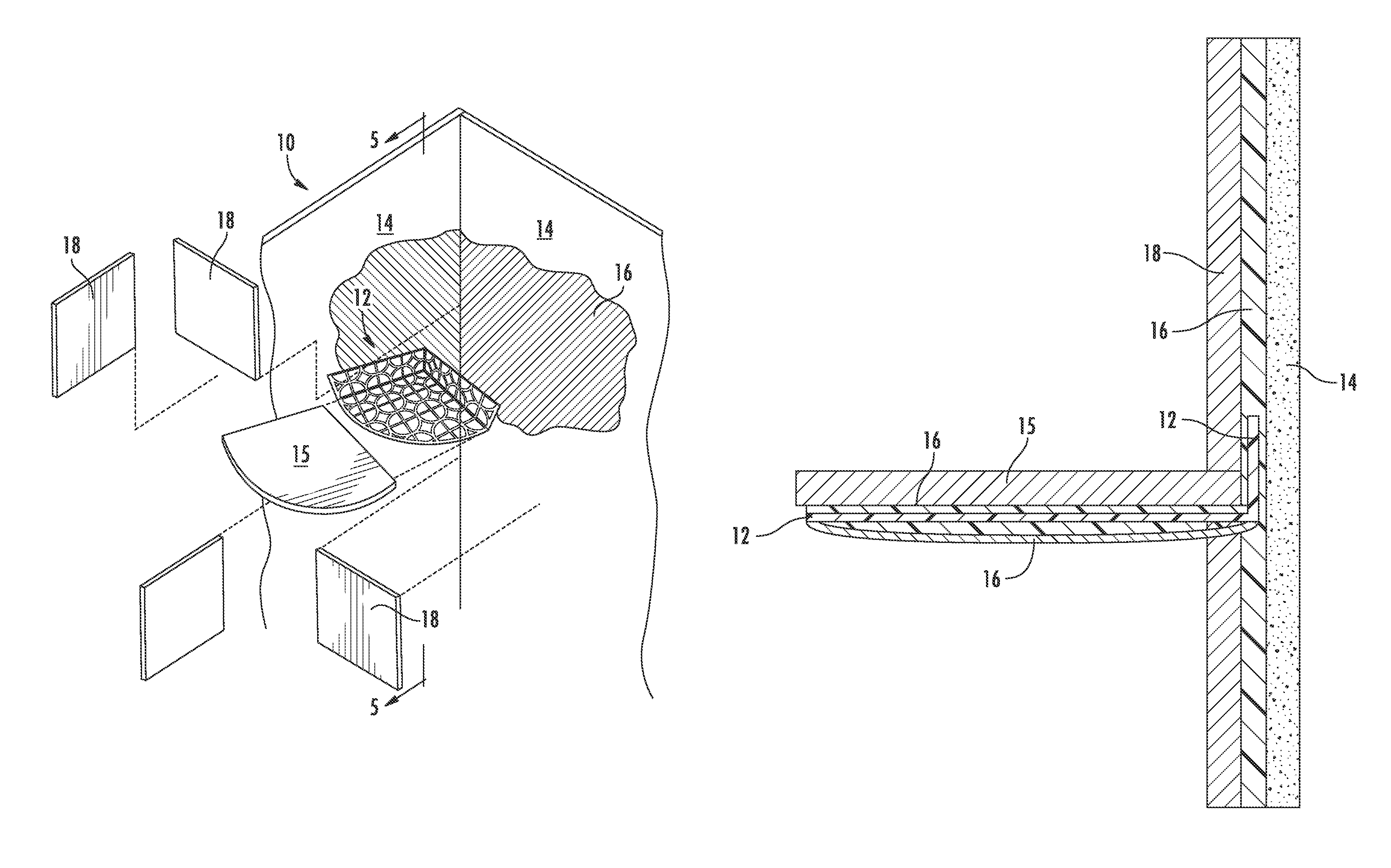
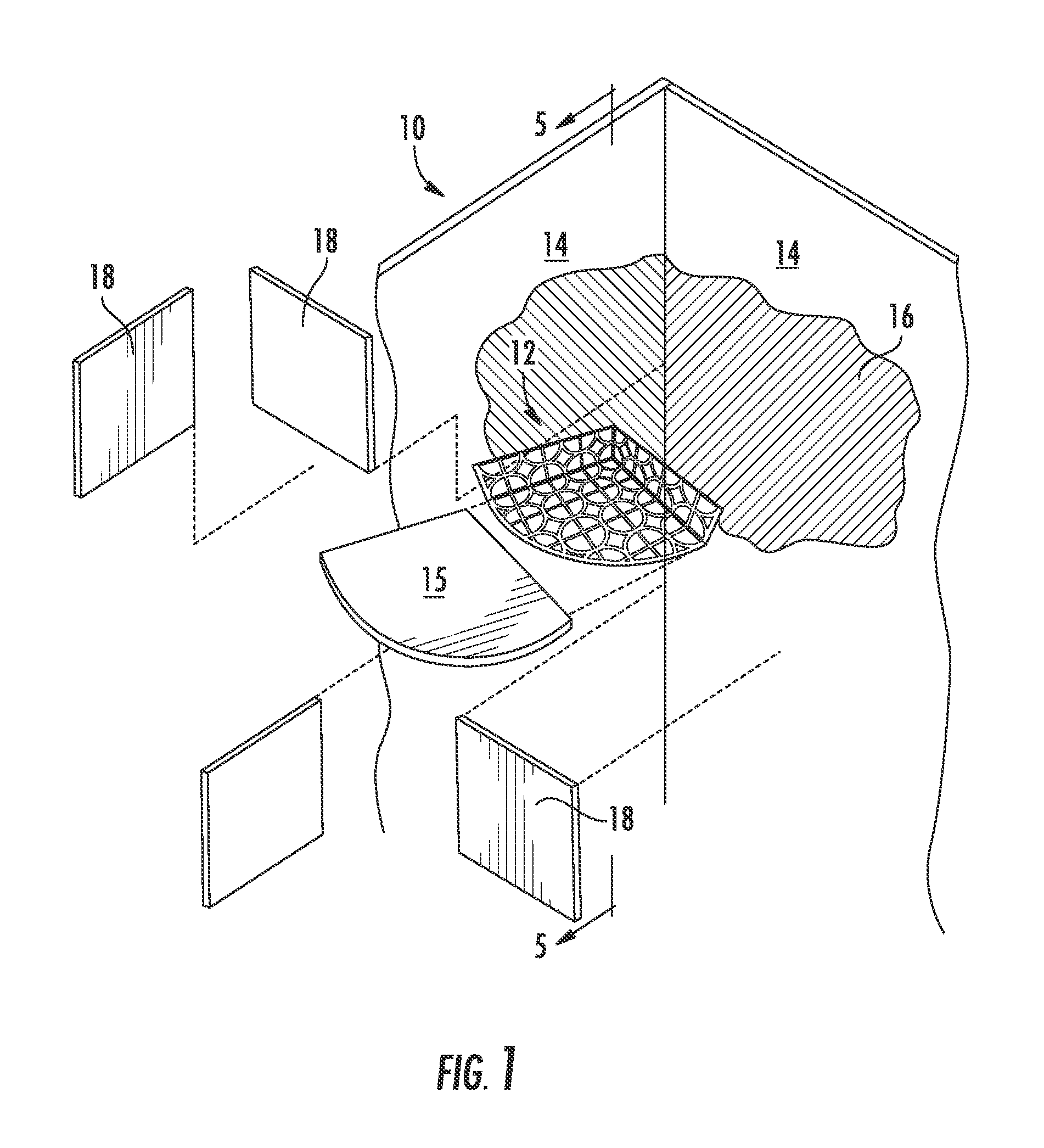
[0028]Referring now to the accompanying drawings and initially to FIG. 1, a tiled wall structure, generally indicated overall at 10, is depicted in exploded form as constructed utilizing an embodiment of the bracket of the present invention, generally indicated that 12, for incorporating a corner seat accessory 15 into the wall structure 10. As is commonplace and well-known to persons of skill in the relevant art, the tiled wall structure 10 basically comprises an upstanding structural substrate 14 of a rigid but porous structural material, a layer of an adhesive mortar applied over the entire surface of the substrate but only representatively indicated at 16 over a portion of the substrate, and an array of decorative tiles adhered to the mortar 16 at uniform edge-spacings over the entire surface of the substrate, as represented by rectangular tiles 18.

[0029]The substrate 14 is of a conventional form typically fabricated of a series of boards or panels of uniform shape and size fixe...


PUM


Abstract

A tiled structure comprises a layer of adhesive mortar, a bracket having a substantially flat base mounting portion with a plurality of perforations embedded in an adhesive mortar with the mortar flowed through the perforations and substantially covering opposite sides of the base mounting portion, and a tile veneer bonded to the adhesive mortar over at least one side of the base mounting portion.

Description

BACKGROUND OF THE INVENTION[0001]The present invention relates generally to the fabrication of tiled structures, particularly vertical tiled structures such as include but are not limited to tiled bathroom and kitchen walls, partitions, doors, drawer fronts, and the like, and relates more particularly to the mounting of accessories on such tiled structures, such as include but are not limited to seats, shelves, other horizontal supports, trays (such as soap trays and dishes), baskets, bars (such a towel bars), rings (such as towel rings), hooks, hangers, knobs, pulls, artwork, and other accessory elements which project outwardly from the tiled structure.[0002]As used herein, the term “tile” is intended to have a broad inclusive meaning as encompassing any and all forms of stone, ceramic, clay, concrete, cement, polymeric, and composite materials, both natural and synthetic, and including those currently known and hereafter developed or discovered, suitable for use in tile veneer app...

Claims


Application Information

Patent Timeline
Patent Type & Authority Patents(United States)
IPC IPC(8): E04F13/08E04F19/00A47K3/00A47K3/024A47K3/16
CPCE04F13/08A47K3/281A47K3/282A47B96/027A47K2201/02A47K10/12A47K10/10
Inventor SCALISE, DAVID H.
Owner SCALISE DAVID H
Learn More