
Blowout preventer with shearing blades

a technology of blowout prevention and shearing blades, which is applied in the direction of drilling pipes, drilling casings, borehole/well accessories, etc., can solve the problems of fish being difficult to retrieve or the bypassed member can become lodged between the shearing blades and damage,

Active Publication Date: 2012-04-24
T 3 PROPERTY HLDG
View PDF100 Cites 9 Cited by
  • Summary
  • Abstract
  • Description
  • Claims
  • Application Information

AI Technical Summary

Benefits of technology

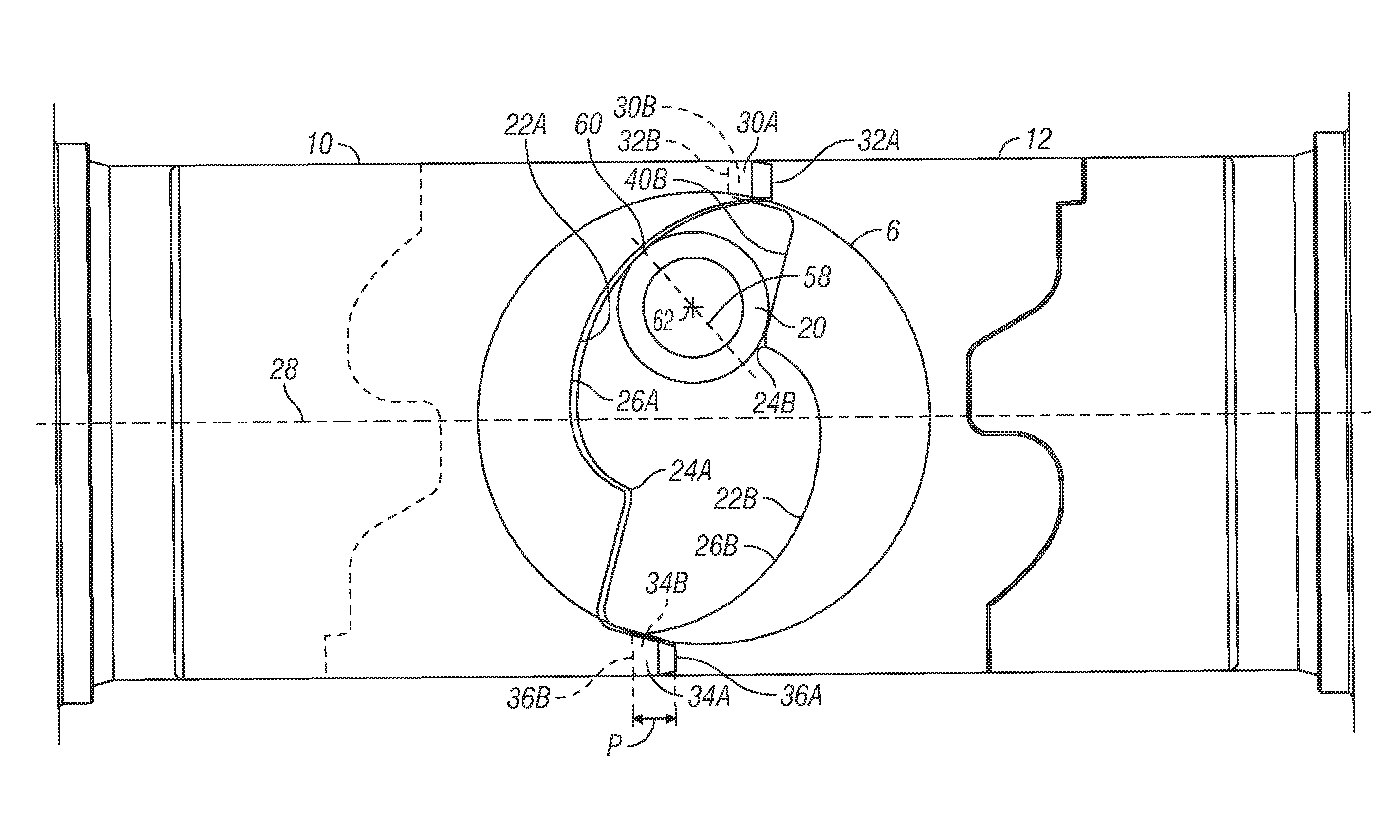
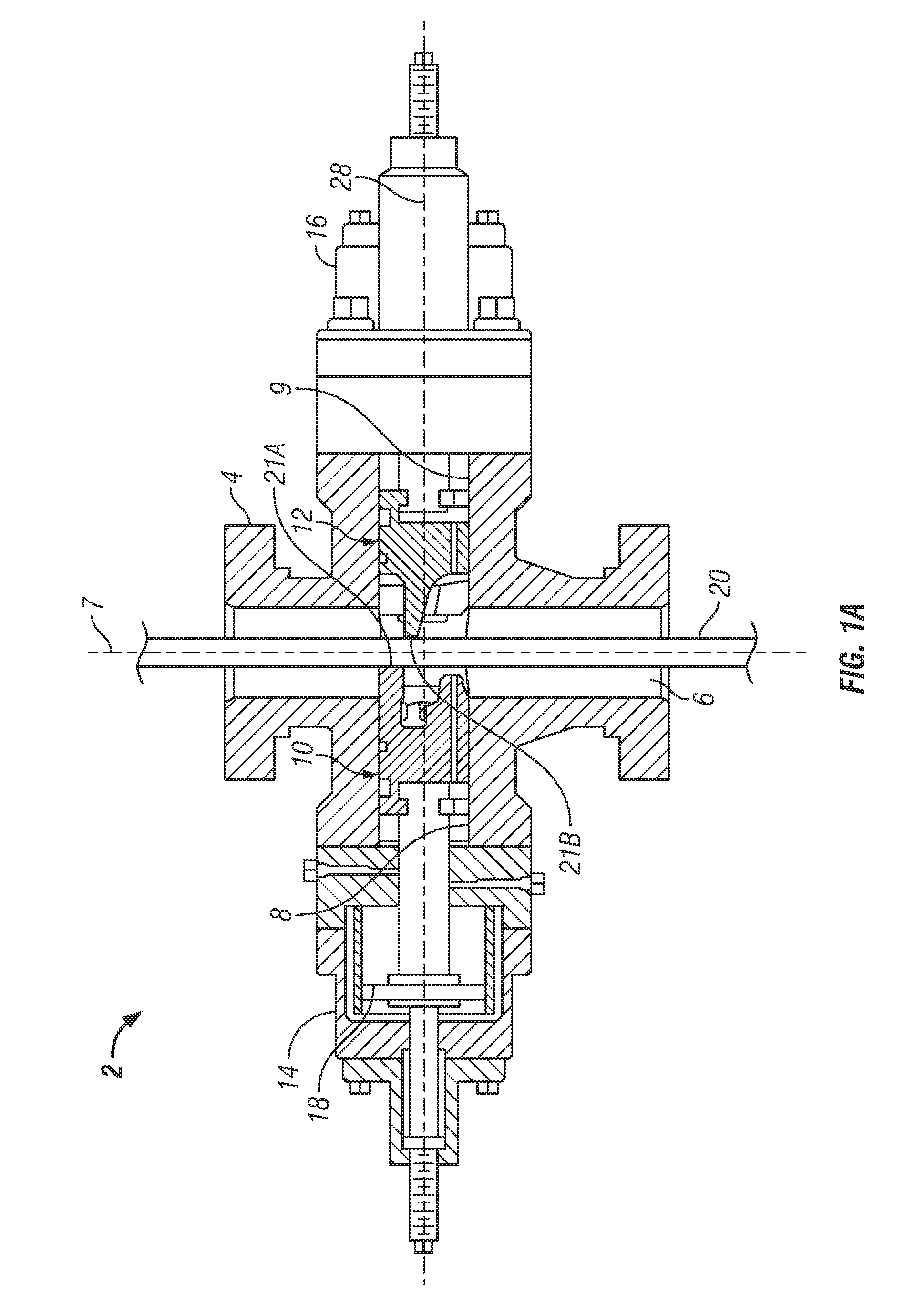
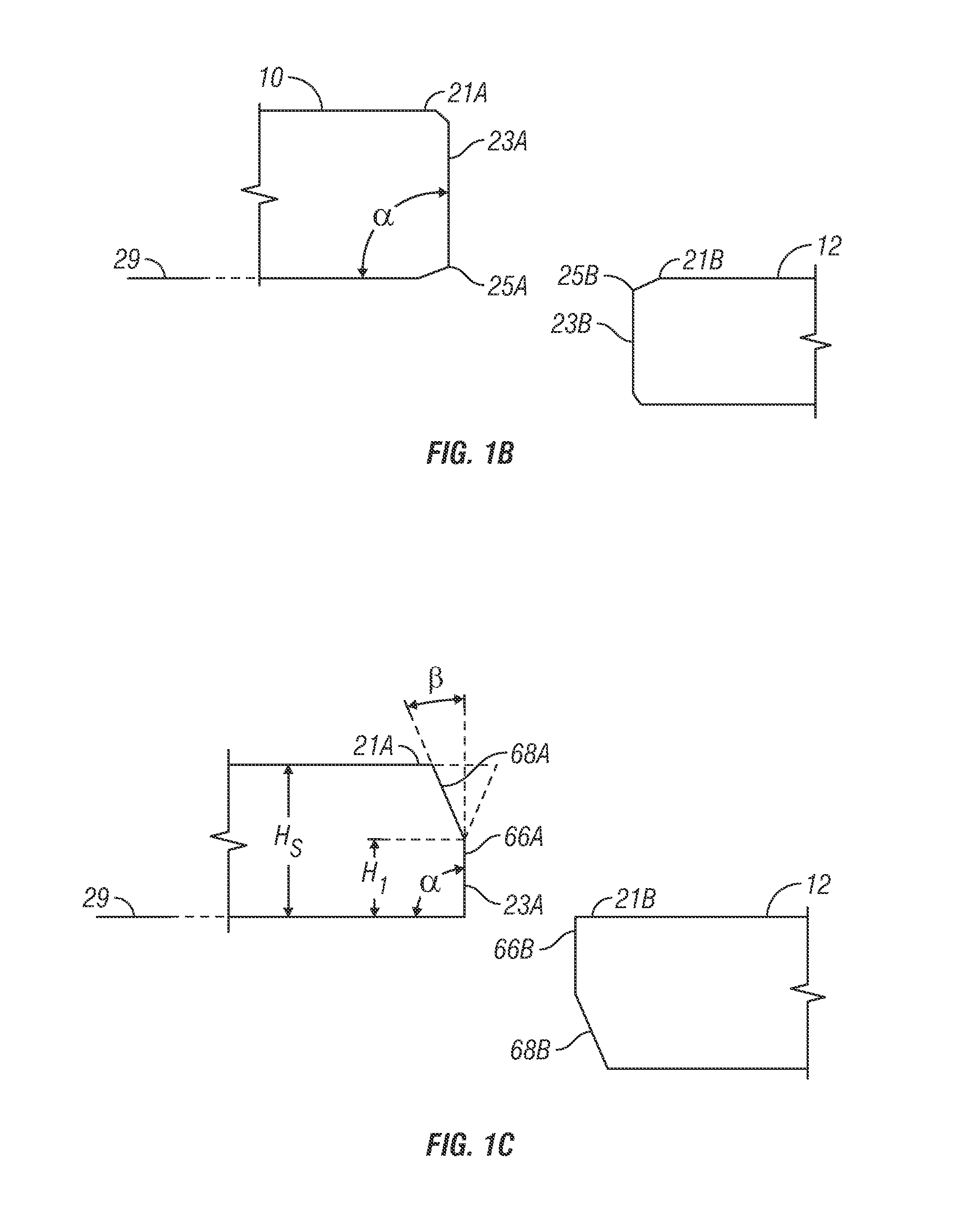
[0012]The disclosure provides a blowout preventer (BOP) system with a ram having a shear blade with a shear blade profile to shear a tubular member disposed in the BOP through-bore. The shear blade profile can include one or more stress concentrators and a centering shaped surface that in some embodiments is asymmetric relative to a centerline of a guideway in the BOP along which the rams close and open around the through-bore. The stress concentrator and the centering shaped surface can be laterally offset from a centerline of the ram travel along the guideway and on opposite sides of the centerline. The profile on one shearing blade can be different from the opposing shearing blade profile. Further, the shearing blade profile can be curved with one or more large radii. The centering shaped surface can extend longitudinally further into the through-bore than the stress concentrator. In at least one embodiment, a first shear blade coupled to a first ram has the shear blade profile, and an opposing second shear blade coupled to an opposing second ram has a mirror image of the shear blade profile with the stress concentrator and centering shaped surface reversed to the orientation of the first shear blade relative to the centerline of the ram travel. Further, the ram can include a mandrel with a mandrel profile that extends into the through-bore at a different elevation than the shear blade profile. The mandrel profile receives an opposing portion of the tubular member from the opposing shear blade. The mandrel profile provides a surface for the tubular member to deform around and reduce an overall lateral width of the separated tubular member in the BOP through-bore to allow retrieval of the deformed separated tubular member from the BOP.

Problems solved by technology

Further, the is bypassed member can become lodged between the shear blades and damage or at least block further movement of the shear blades.
A further challenge in typical BOPs is the ability to retrieve the sheared tubular member also termed a “fish.” The fish is created by deforming the tubular member into a substantially flattened shape initially between the shearing blades, and then shearing the tubular member with the BOP.
Sometimes, the fish can be difficult to retrieve or can become stuck in the attempt to retrieve.

Method used


Image

  • Blowout preventer with shearing blades
  • Blowout preventer with shearing blades
  • Blowout preventer with shearing blades

Examples


Embodiment Construction

[0034]The Figures described above and the written description of specific structures and functions below are not presented to limit the scope of what Applicant has invented or the scope of the appended claims. Rather, the Figures and written description are provided to teach any person skilled in the art to make and use the inventions for which patent protection is sought. Those skilled in the art will appreciate that not all features of a commercial embodiment of the inventions are described or shown for the sake of clarity and understanding. Persons of skill in this art will also appreciate that the development of an actual commercial embodiment incorporating aspects of the present disclosure will require numerous implementation-specific decisions to achieve the developer's ultimate goal for the commercial embodiment. Such implementation-specific decisions may include, and likely are not limited to, compliance with system-related, business-related, government-related and other con...


PUM


Abstract

The disclosure provides a blowout preventer (BOP) system with a ram having a shear blade with a shear blade profile to shear a tubular member disposed in the BOP. The shear blade profile can include a stress concentrator and centering shaped surface. The stress concentrator and the centering shaped surface can be laterally offset from a centerline of ram travel and on opposite sides of the centerline. An opposing second shear blade can have a mirror image of the shear blade profile with the stress concentrator and centering shaped surface reversed to the orientation of the first shear blade. Further, the ram can include a mandrel with a mandrel profile for the tubular member to deform around during the shearing process and to reduce an overall lateral width of the sheared tubular member in the BOP through-bore to allow retrieval of the deformed sheared tubular member from the BOP.

Description

CROSS REFERENCE TO RELATED APPLICATIONS[0001]This application claims the benefit of U.S. Provisional Application No. 61 / 374,258, filed on Aug. 17, 2010, and U.S. Provisional Application No. 61 / 475,533 filed on Apr. 14, 2011.STATEMENT REGARDING FEDERALLY SPONSORED RESEARCH OR DEVELOPMENT[0002]Not applicable.REFERENCE TO APPENDIX[0003]Not applicable.BACKGROUND OF THE INVENTION[0004]1. Field of the Invention[0005]The disclosure generally relates oil field equipment. More particularly, the disclosure relates to the blowout preventers.[0006]2. Description of the Related Art[0007]In gas and oil wells, it is sometimes necessary to shear a tubular member disposed therein and seal the wellbore to prevent an explosion or other mishap from subsurface pressures. Typically, the oil field equipment performing such a function is known as a blowout preventer (“BOP”). A BOP has a body that typically is mounted above a well as equipment in a BOP stack.[0008]A typical BOP has a body with a through-bor...

Claims


Application Information

Patent Timeline
Patent Type & Authority Patents(United States)
IPC IPC(8): E21B33/06
CPCE21B33/063
Inventor JAHNKE, DOUGLAS
Owner T 3 PROPERTY HLDG
Learn More