Integrated cleaning and drying mop bucket

An all-in-one, mop bucket technology, which is applied in the direction of cleaning carpets, floors, cleaning equipment, etc., can solve the problems of large space occupation, inconvenient storage and movement, etc., and achieve small space occupation, convenient storage and movement, and reduced horizontal width Effect

Inactive Publication Date: 2015-10-28
胡松阳
View PDF7 Cites 8 Cited by
  • Summary
  • Abstract
  • Description
  • Claims
  • Application Information

AI Technical Summary

Problems solved by technology

However, since the cleaning head and the drying disc are located on both sides of the inner cavity of the barrel body, the transverse width of the barrel body is forced to be wider, which takes up a lot of space and is not convenient for storage and movement.

Method used


Image

  • Integrated cleaning and drying mop bucket
  • Integrated cleaning and drying mop bucket

Examples


Embodiment Construction

[0014] The following descriptions are only preferred embodiments of the present invention, and therefore do not limit the protection scope of the present invention.

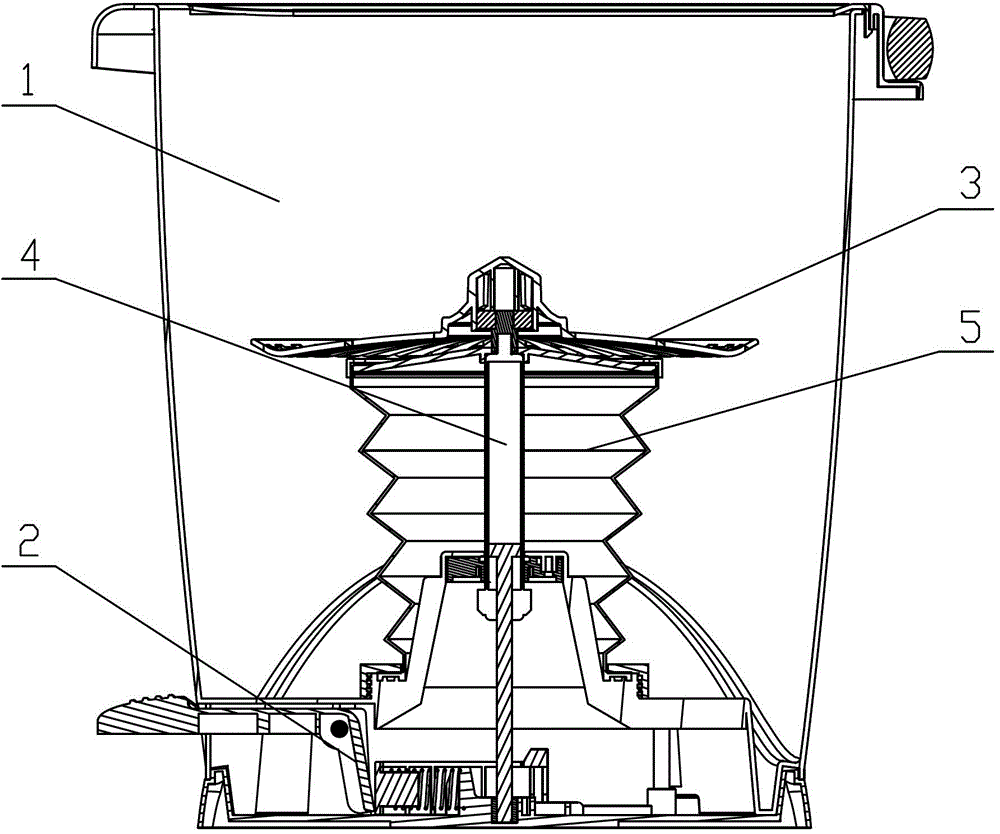
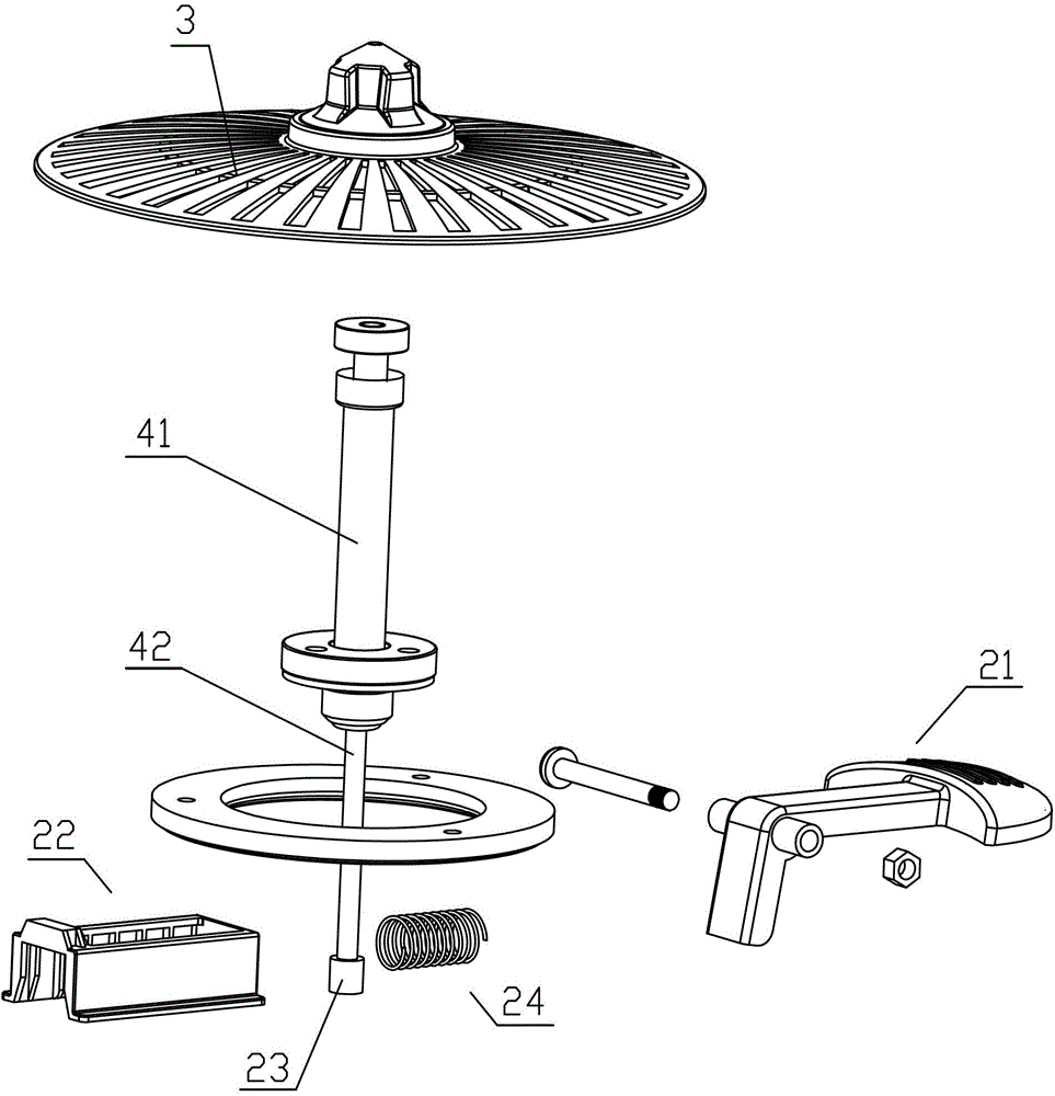
[0015] Examples, see figure 1 with figure 2 Shown: an integrated cleaning and drying mop bucket, including a bucket body 1, a power unit 2 and a drying tray 3. A synchronously rotating telescopic tube 4 is pivotally connected to the bottom of the inner cavity of the bucket body 1 , and the power unit 2 is connected to the bottom end of the synchronously rotating telescopic tube 4 , and the drying disc 3 is fixed to the top end of the synchronously rotating telescopic tube 4 . Wherein, the so-called synchronously rotating telescopic cylinder 4 means that when one end of the telescopic cylinder rotates, the other end of the telescopic cylinder is driven to rotate simultaneously. Its form can take many common forms, for example, a spring is provided between the two ends of the telescopic cylinder, and an anti-rot...


PUM


Abstract

The invention discloses an integrated cleaning spin-dry mop bucket, which comprises a bucket body, a power device and a spin-dry disk, wherein a synchronous rotating telescopic barrel is pivoted at the bottom of the inner cavity of the bucket body; the power device is connected to the bottom end of the synchronous rotating telescopic barrel; and the spin-dry disk is fixed at the top end of the synchronous rotating telescopic barrel. Preferably, the synchronous rotating telescopic barrel comprises an air-pressure barrel, wherein the top end of the air-pressure barrel is enclosed; the lower end of the air-pressure barrel is opened, and a telescopic shaft extends out of the lower end of the air-pressure barrel; the top end of the telescopic shaft is hermetically connected with the inner wall of the air-pressure barrel; and meanwhile, an anti-rotation positioning device is arranged between the telescopic shaft and the air-pressure barrel. After the adoption of the structure, the integrated cleaning spin-dry mop bucket has the advantages that: the bucket body occupies a small space, and is convenient to accommodate and move.

Description

technical field [0001] The invention relates to the technical field of cleaning devices, in particular to an integrated cleaning and drying mop bucket. Background technique [0002] A kind of mop bucket that can clean and dry the mop head that occurs now. It includes a bucket body, one side of the inner cavity bottom of the bucket body is provided with a drying tray (or drying basket), and the other side is provided with a cleaning head. Of course, the drying disc is connected with a power device, and the level of the drying disc is higher than that of the cleaning head. Like this, put into bucket body the water that level is higher than cleaning head but is lower than spin-drying disc, then mop head is placed on cleaning head and can clean mop head, mop head is placed on the drying disc and can dry mop head, Extremely convenient. However, since the cleaning head and the spin-drying disc are located on both sides of the inner chamber of the barrel respectively, the transv...

Claims


Application Information

Patent Timeline
Patent Type & Authority Patents(China)
IPC IPC(8): A47L13/58
Inventor 胡松阳
Owner 胡松阳
Why Eureka
Try Eureka