Intra-annular mounting frame for aortic valve repair

a technology for aortic valves and mounting frames, which is applied in the field of mounting frames, can solve the problems of aortic valve disease repair not being met with the same success as reconstructing, aortic valve disease repair and aortic valve disease not being repaired with the same success. , to achieve the effect of reducing the risk of recurrent aortic insufficiency, reducing the risk of recurrent aorti

Active Publication Date: 2012-04-24
BIOSTABLE SCI & ENG
View PDF25 Cites 33 Cited by
  • Summary
  • Abstract
  • Description
  • Claims
  • Application Information

AI Technical Summary

Benefits of technology

[0022]With the model, the two above sets of equations can be solved to determine the points of intersection of the cusps with each other and with the aorta so as to produce a model having points of intersection as in FIG. 2a. Such model divides the aortic circumference into thirds, allows the cusps to meet centrally, and produces lateral overlap of the cusps in the same “coaptation crescent” as observed in the dissected specimens. Similarly, the results can be plotted to illustrate the intersection of a plane perpendicular to the axis of the aorta and the leaflets at multiple levels, and by stacking multiple 2-dimensional pictures, the 3-dimensional anatomy of the aortic valve leaflets can be viewed from above the valve as in FIG. 2b and from below the valve as illustrated in FIG. 2c. Furthermore, because the center of the base of the valve cusp hemispheres intersect the cylindrical aorta at the origin and the three valve cusp hemispheres each span approximately ⅓ of the circumference of the cylindrical aorta, a “shield shape” is produced for each cusp as illustrated in FIG. 3. Using this model, the 3-dimensional geometry of the normal aortic valve annulus can be determined using simple mathematics, by determining the intersections of the cusp hemispheres with the aortic cylinder.
[0028]Generally, the intra-annular hemispherical mounting frame can be implanted into the aortic valve annulus in a variety of ways. A first method includes small fabric strips, pledgets, or pads with a combination of mattress sutures to firmly suture the intra-annular hemispherical mounting frame to the aortic valve annulus, while reducing tearing of the aortic tissue. Alternatively, complementary single cusp arcs with curvatures similar to the multiple shield curves may be employed above the cusps into which sutures may be inserted so that the patient's cusps would be “sandwiched” between the semi-rigid intra-annular hemispherical mounting frame and the supporting arcs above.
[0032]Another object of the invention is an intra-annular hemispherical mounting frame having posts corresponding to each interconnecting point which assists in suspending the commissures and cusps in a proper three-dimensional relationship.

Problems solved by technology

Eventually, a central gap of coaptation occurs and increasing aortic insufficiency begets more annular dilatation which begets more aortic insufficiency and the leak progressively increases.
Repair of a diseased aortic valve has not been met with the same success as experienced in reconstructing a diseased mitral valve.
There is a limit, however, to the geometric abnormality that commissural annuloplasty can normalize, and because the entire annulus is not fixed by this procedure, the potential for further dilatation and recurrent aortic insufficiency exists.
Furthermore, as the ring of the '602 patent is apparently based on previous studies of the mitral valve, the '602 neglects the complexities of the 3-dimensional geometry of the aortic valve and ineffectively constricts either the supra-valvular or infra-valvular area.
Unfortunately, supra- or infra-annular rings and artificial valves of the prior art processes are generally not effective for the long term improvement of the aortic valve, and additionally, may require quite complicated surgical procedures.
Suturing a ring below the aortic valve (infra-annular) to simply downsize or constrict the circumference will negatively distort the valve cusps and can lead to worsening valve leak.
Similarly, the supra-annular rings of the prior art are laden with the same problems, and have even less geometric basis, since the supra-annular rings only quite roughly follow the shape of the aortic tissue above the annulus and are based on no tangible geometric model.

Method used


Image

  • Intra-annular mounting frame for aortic valve repair
  • Intra-annular mounting frame for aortic valve repair
  • Intra-annular mounting frame for aortic valve repair

Examples


Embodiment Construction

[0054]Although the products and methods according to the present invention are disclosed herein as being useful for and in the context of aortic valve repair, both the products and methodology may also be used in other fields including, but not limited to, surgical procedures for the repair of other valves within the human body.

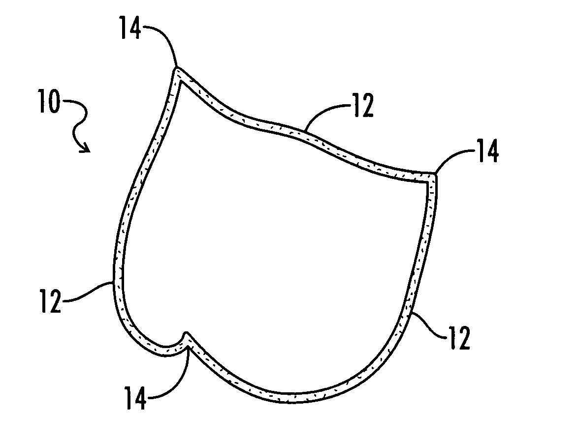
[0055]Referring generally now to FIG. 4, an intra-annular hemispherical mounting frame useful for aortic valve repair is shown and generally designated as numeral 10. Intra-annular hemispherical mounting frame 10 is inserted into the aortic valve annulus and provides for the reconstruction of the native aortic valve.

[0056]Intra-annular hemispherical mounting frame 10 includes a plurality of curvatures 12 and also interconnecting points 14. Generally, curvature 12 conforms to the annular cusp geometry with interconnecting points 14 conforming to the geometry of the commissures. Curvatures 12 curve in about a first plane and a second plane of hemispherical moun...


PUM


Abstract

An intra-annular mounting frame for an aortic valve having native aortic cusps is provided which includes a frame body with native leaflet reorienting curvatures and interconnecting points; the curvatures shaped to be received inside the valve below the native aortic cusps and to reorient the native aortic cusps within the aortic valve, where each of the curvatures extends concavely upward from a reference latitudinal plane tangential to each curvature's base.

Description

[0001]The present application is a continuation of and claims benefit of our U.S. provisional patent application Ser. No. 60 / 849,919, entitled “Intra-Annular Ring For Aortic Valve Repair” filed Oct. 6, 2006 and is hereby incorporated by reference. Additionally all patents and publications described or discussed herein are hereby incorporated by reference in their entireties.BACKGROUND OF THE INVENTION[0002]1. Technical Field[0003]The present invention relates to a mounting frame useful for applications including aortic valve repair. More particularly, the present invention relates to an intra-annular mounting frame which is inserted directly into the aortic valve annulus. The invention also includes methods for the insertion and implantation of the intra-annular mounting frame, as well as complementary devices, such as ascending aortic Dacron® grafts and pericardial single cusp prostheses.[0004]2. Background of the Art[0005]The mammalian heart is essentially a pump that functions as...

Claims


Application Information

Patent Timeline
Patent Type & Authority Patents(United States)
IPC IPC(8): A61F2/24
CPCA61F2/2418A61F2/2445A61F2/24A61F2/2409A61F2210/0071A61F2240/002A61F2/2442
Inventor RANKIN, J. SCOTT
Owner BIOSTABLE SCI & ENG
Why Eureka
Try Eureka