
Method and apparatus for measuring a parameter of a vehicle electrical system

a technology of electrical parameters and vehicle electrical systems, applied in the direction of impedence measurements, line-transmission details, instruments, etc., can solve the problems of relatively small cable resistance and typically inability to measur

Active Publication Date: 2012-04-24
MIDTRONICS
View PDF731 Cites 59 Cited by
  • Summary
  • Abstract
  • Description
  • Claims
  • Application Information

AI Technical Summary

Benefits of technology

The patent describes a device that tests the electrical system of a car by measuring the electrical properties of the wiring that connects the car's battery to its electrical load. The device has a connection to the battery and a connection to the wiring, and it uses the battery to draw current through the wiring and measure its electrical properties. The technical effect of this device is to provide a reliable and efficient way to test the electrical system of a car to ensure it is functioning properly.

Problems solved by technology

Because the cable resistance is relatively small it typically cannot be measured using a standard ohm meter or other techniques which are normally used to measure resistance.
However, this is cumbersome and requires components capable of handling the large current.

Method used


Image

  • Method and apparatus for measuring a parameter of a vehicle electrical system
  • Method and apparatus for measuring a parameter of a vehicle electrical system
  • Method and apparatus for measuring a parameter of a vehicle electrical system

Examples


Embodiment Construction

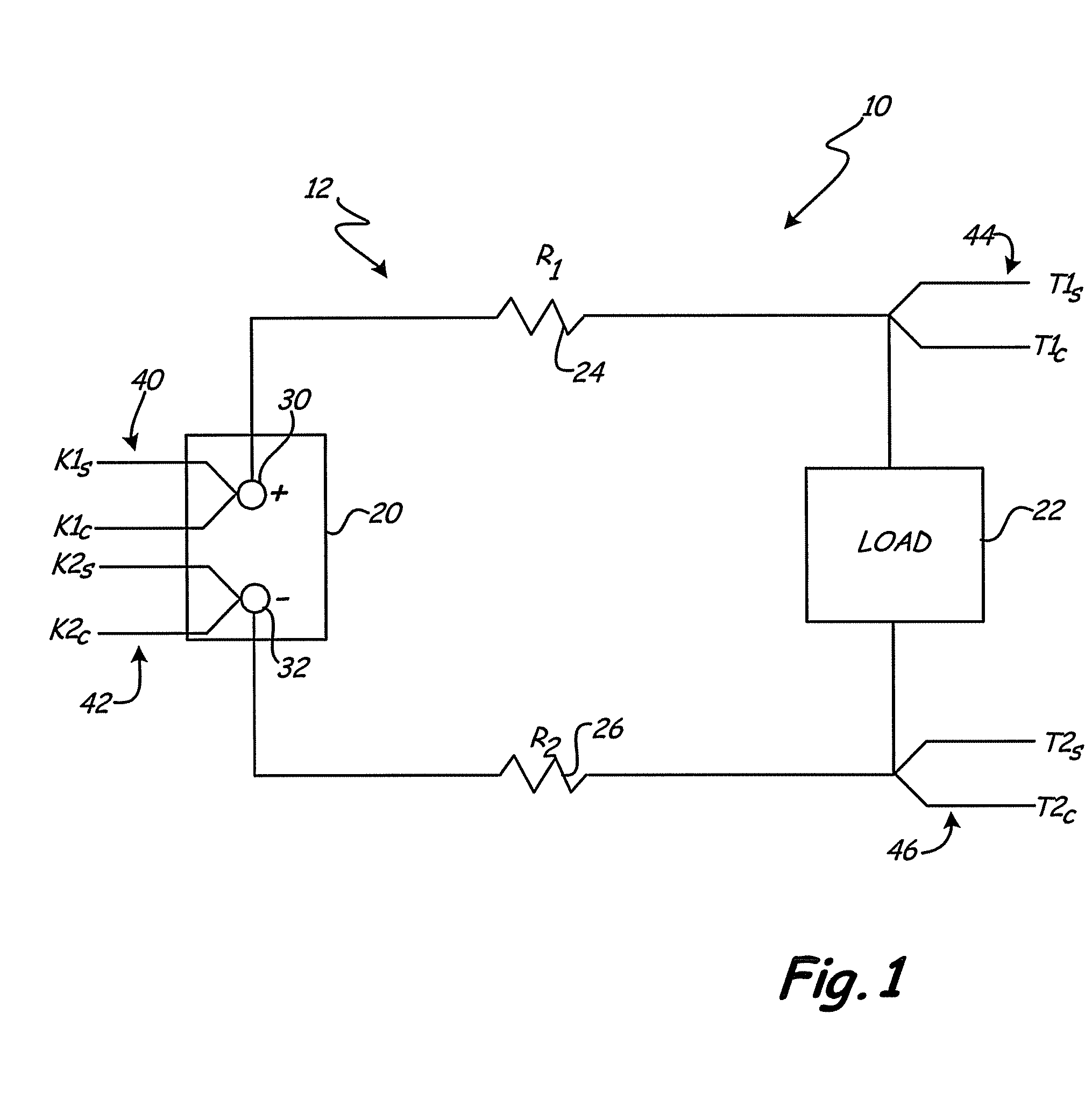
[0015]FIG. 1 is a simplified diagram of an electrical system 10 of a vehicle 12. Electrical system 10 includes a battery 20, a load 22 and cables 24 and 26 which connect load 22 to the positive terminal 30 of battery 20 and the negative terminal 32 of battery 20, respectively. Cables 24 and 26 are illustrated as having resistances R1 and R2, respectively.

[0016]FIG. 1 also shows Kelvin connections 40 and 42 coupled to the positive terminal 30 and the negative terminal 32 of battery 20 respectively.

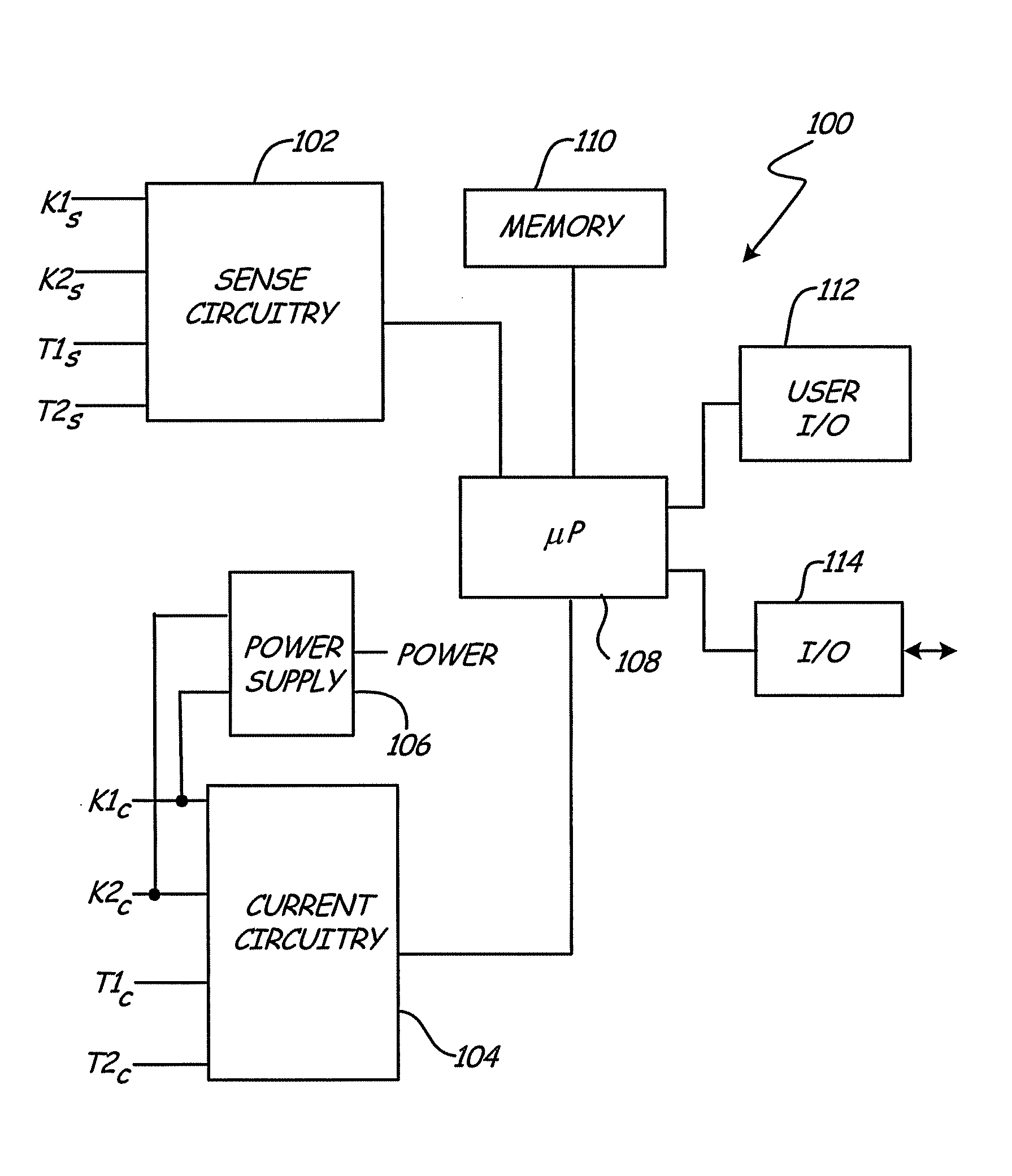
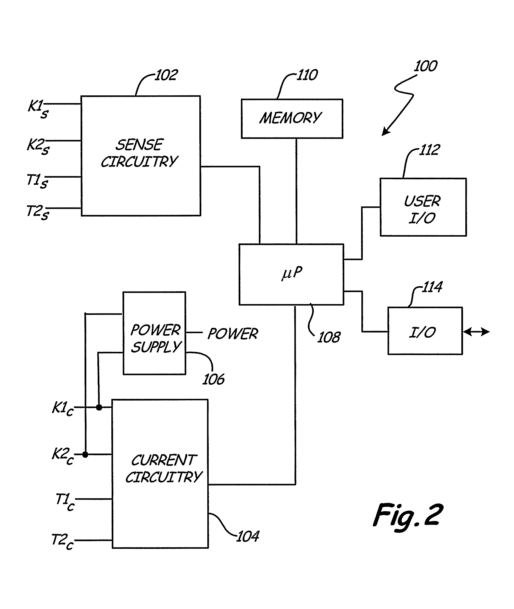
[0017]Kelvin connection 40 has a sense connection K1S and a current connection K1C. Similarly, Kelvin connection 42 has a sense connection K2S and a current connection K2C. FIG. 1 also illustrates test connections 44 and 46. In the embodiment of FIG. 1, these are illustrated as being Kelvin connections, however the present invention is not limited to this arrangement. Test connection 44 is connected between load 22 and cable 24. Similarly, test connection 46 is connected between load 22 and...


PUM


Abstract

An automotive vehicle electrical system tester is provided for testing an electrical system having wiring which couple a load to a battery. The automotive vehicle electrical system tester is configured to measure an electrical parameter of the wiring and includes a first battery terminal connection configured to couple to a first terminal of the battery. A test connection is configured to couple to a wire of the electrical system which extends between the first terminal of the battery and the load. Test circuitry coupled to the first battery terminal connection and the test connection is configured to draw current from the battery along a path through the wire and to the test connection. The test circuitry measures an electrical parameter of the wire.

Description

[0001]The present application is a Continuation-In-Part of and claims priority of U.S. patent application Ser. No. 11 / 641,594, filed Dec. 19, 2006, which is a Divisional of U.S. patent application Ser. No. 10 / 656,526, filed Sep. 5, 2003, now U.S. Pat. No. 7,154,276, the contents of which are hereby incorporated by reference in their entirety.BACKGROUND OF THE INVENTION[0002]The present invention relates to the measurement of electrical parameters of a vehicle electrical system. More specifically, the present invention relates to measuring an electrical parameter of an electrical system of a vehicle using a plurality of connections to the electrical system.[0003]Various types of devices related to battery tester, vehicle diagnostics and the like are described in U.S. Pat. No. 3,873,911, issued Mar. 25, 1975, to Champlin; U.S. Pat. No. 3,909,708, issued Sep. 30, 1975, to Champlin; U.S. Pat. No. 4,816,768, issued Mar. 28, 1989, to Champlin; U.S. Pat. No. 4,825,170, issued Apr. 25, 1989...

Claims


Application Information

Patent Timeline
Patent Type & Authority Patents(United States)
IPC IPC(8): G01R31/00G01R31/02G01R27/08
CPCG01R31/006G01R31/007G01R27/14G01R27/16G01R31/021G01R31/58
Inventor BERTNESS, KEVIN I.
Owner MIDTRONICS
Learn More