Image forming apparatus having a first coupling and a second coupling
a technology of image forming apparatus and coupling, which is applied in the direction of electrographic process apparatus, yielding coupling, instruments, etc., can solve the problems of increasing cost, deteriorating the operation of opening and closing the cover, and increasing the load for disengaging and engaging the coupling, so as to increase the rigidity of the cover, increase the size of the link mechanism itself, and increase the rigidity
- Summary
- Abstract
- Description
- Claims
- Application Information
AI Technical Summary
Benefits of technology
Problems solved by technology
Method used
Image
Examples
embodiment 1
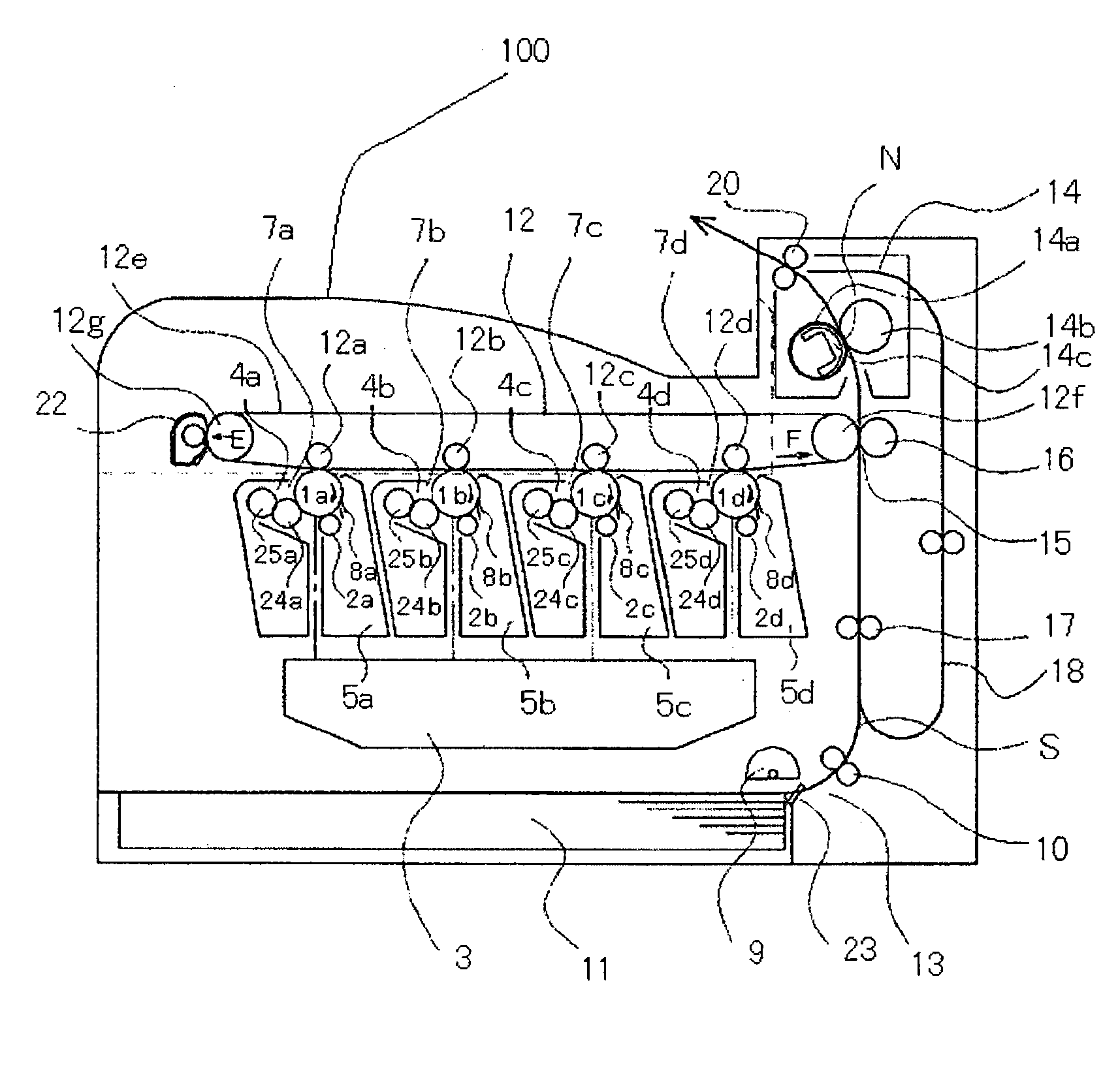
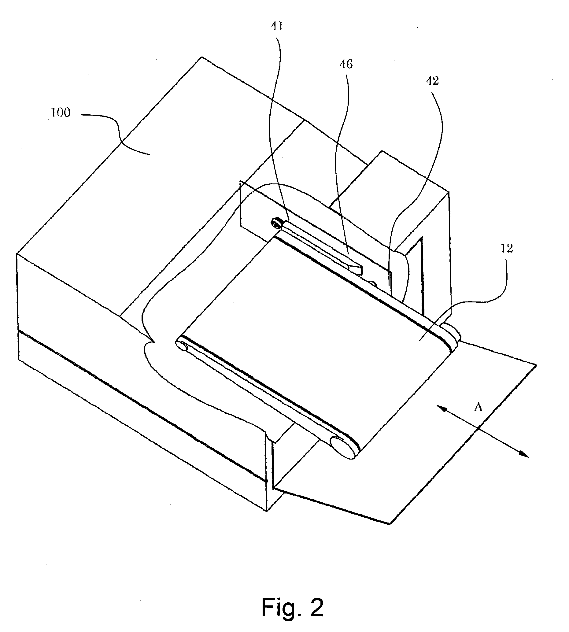
[0045]This embodiment will be described by using a four-drum type color image forming apparatus of an electrophotographic type as an apparatus main assembly and using an intermediary transfer unit as a detachably mountable unit. Further, in this embodiment, in order to transmit from the apparatus main assembly a driving force for moving a primary transfer roller in the intermediary transfer unit away from a corresponding photosensitive drum, a drive transmission device is used. The drive transmission device in this embodiment includes a first coupling and a second coupling rotating by being engaged with the first coupling.
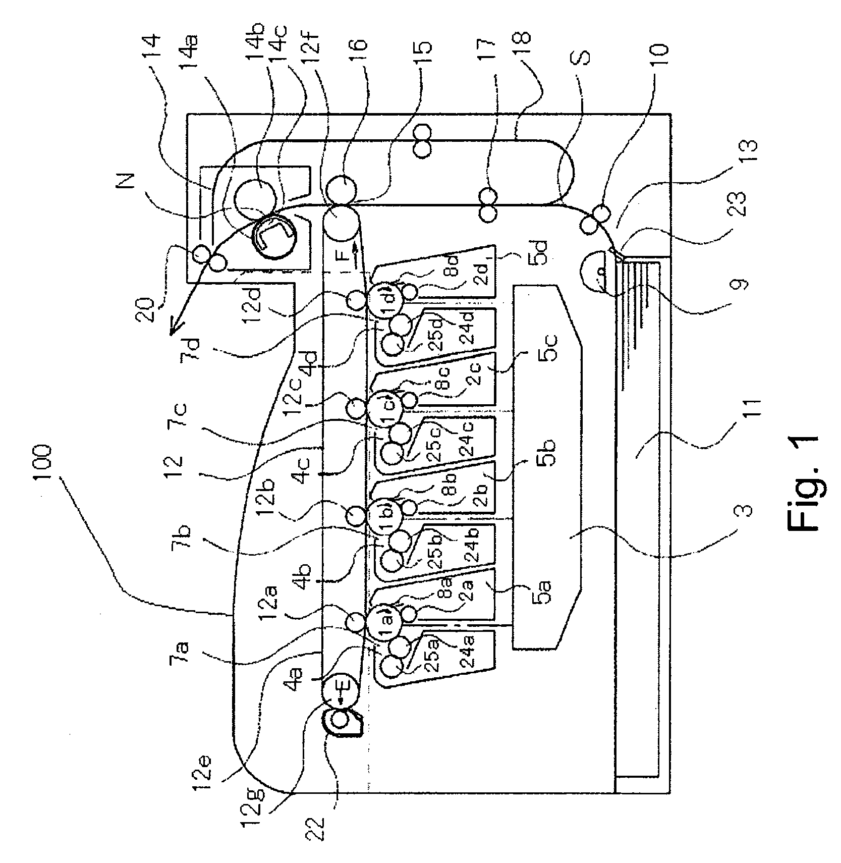
[0046]Hereinbelow, an embodiment of the present invention will be described in the order of the image forming apparatus, the intermediary transfer unit, and the drive transmission device with reference to FIGS. 1 to 12.
[Image Forming Apparatus]
[0047]First, a constitution of an apparatus main assembly 100 will be described.
[0048]FIG. 1 is a sectional view showing an...
embodiment 2
[0094]In this embodiment, a drive transmission device in which a driving cartridge 51 and a driven cartridge 52 are engaged with each other at a plurality of phases will be described. All the constitutions other than the drive transmission device are similar to those in Embodiment 1.
[0095]In the case where there is no need to control the phase on an objective unit side by the driving motor provided on the main assembly side, a similar effect can be obtained also in the constitution of the couplings shown in FIGS. 13(a) to 13(c). For example, a drive transmission device or the like for rotating unit-side rollers or the like in a predetermined direction corresponds to the constitution.
[0096]In FIGS. 13(a) to 13(c), a reference numeral 51 represents a driving cartridge corresponding to the driving cartridge 4 in Embodiment 1 and a reference numeral 52 represents a driven cartridge corresponding to the driven cartridge 42 in Embodiment 1.
[0097]The couplings in this embodiment are simila...
embodiment 3
[0101]In this embodiment, a drive transmission device in which a driving cartridge 61 and a driven cartridge 62 are engaged with each other at a plurality of phases will be described. All the constitutions other than the drive transmission device are similar to those in Embodiment 1.
[0102]Similarly as in Embodiment 2, the drive transmission device can be used in the case where there is no need to control the phase on an objective unit side by the driving motor provided on the main assembly side.
[0103]In FIGS. 18(a) to 18(c), a reference numeral 61 represents a driving cartridge corresponding to the driving cartridge 4 in Embodiment 1 and a reference numeral 62 represents a driven cartridge corresponding to the driven cartridge 42 in Embodiment 1.
[0104]The couplings in this embodiment are similar to those in Embodiment 1 except that engaging portions of the driving cartridge 61 and the driven cartridge 62 are different in shape from the couplings in Embodiment 1.
[0105]As shown in FIG...
PUM
 Abstract
Description
Claims
Application Information
 - R&D
- Intellectual Property
- Life Sciences
- Materials
- Tech Scout
- Unparalleled Data Quality
- Higher Quality Content
- 60% Fewer Hallucinations
Browse by: Latest US Patents, China's latest patents, Technical Efficacy Thesaurus, Application Domain, Technology Topic, Popular Technical Reports.
© 2025 PatSnap. All rights reserved.Legal|Privacy policy|Modern Slavery Act Transparency Statement|Sitemap|About US| Contact US: help@patsnap.com


