

Bit mounting devices
a technology of mounting device and bit, which is applied in the direction of chucks, mechanical equipment, manufacturing tools, etc., can solve the problems that the magnetic connecting bits of the most popularly incorporated stopper ring engagement system cannot be used, and the technique does not have a direct relation with the construction of mounting the tool bit itsel
- Summary
- Abstract
- Description
- Claims
- Application Information
AI Technical Summary
Benefits of technology
Problems solved by technology
Method used
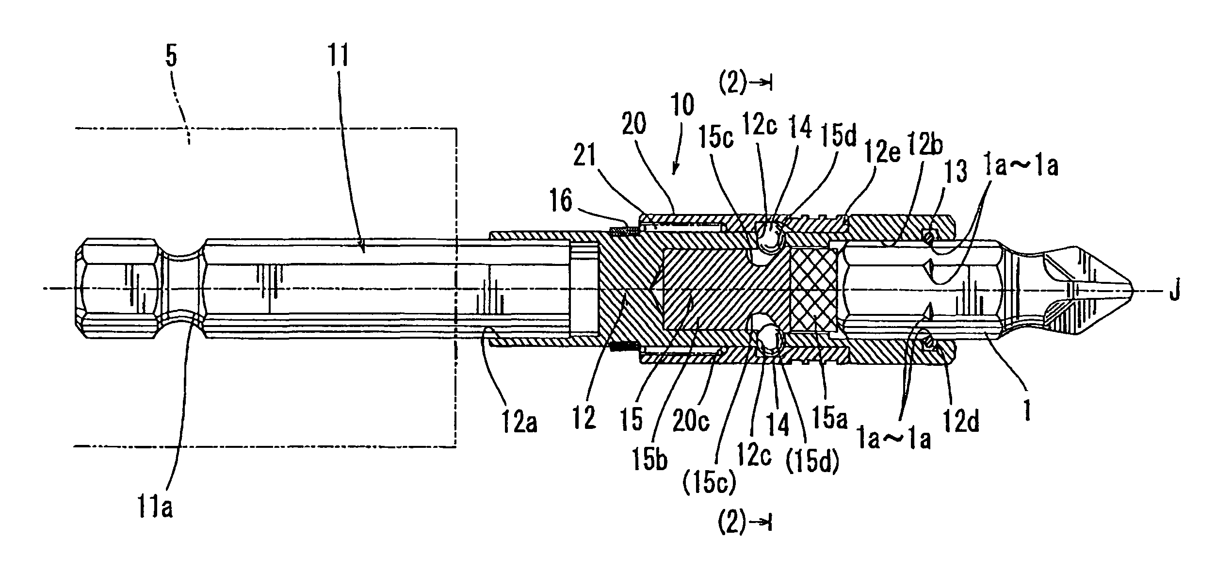
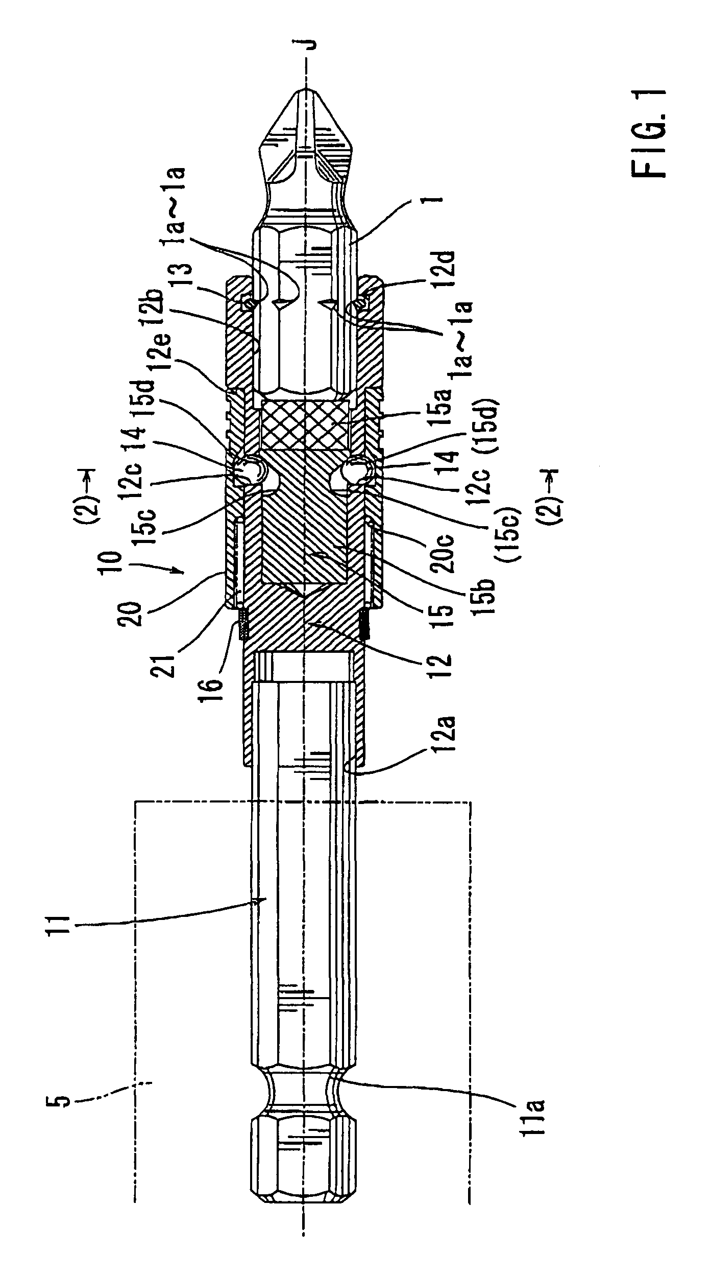
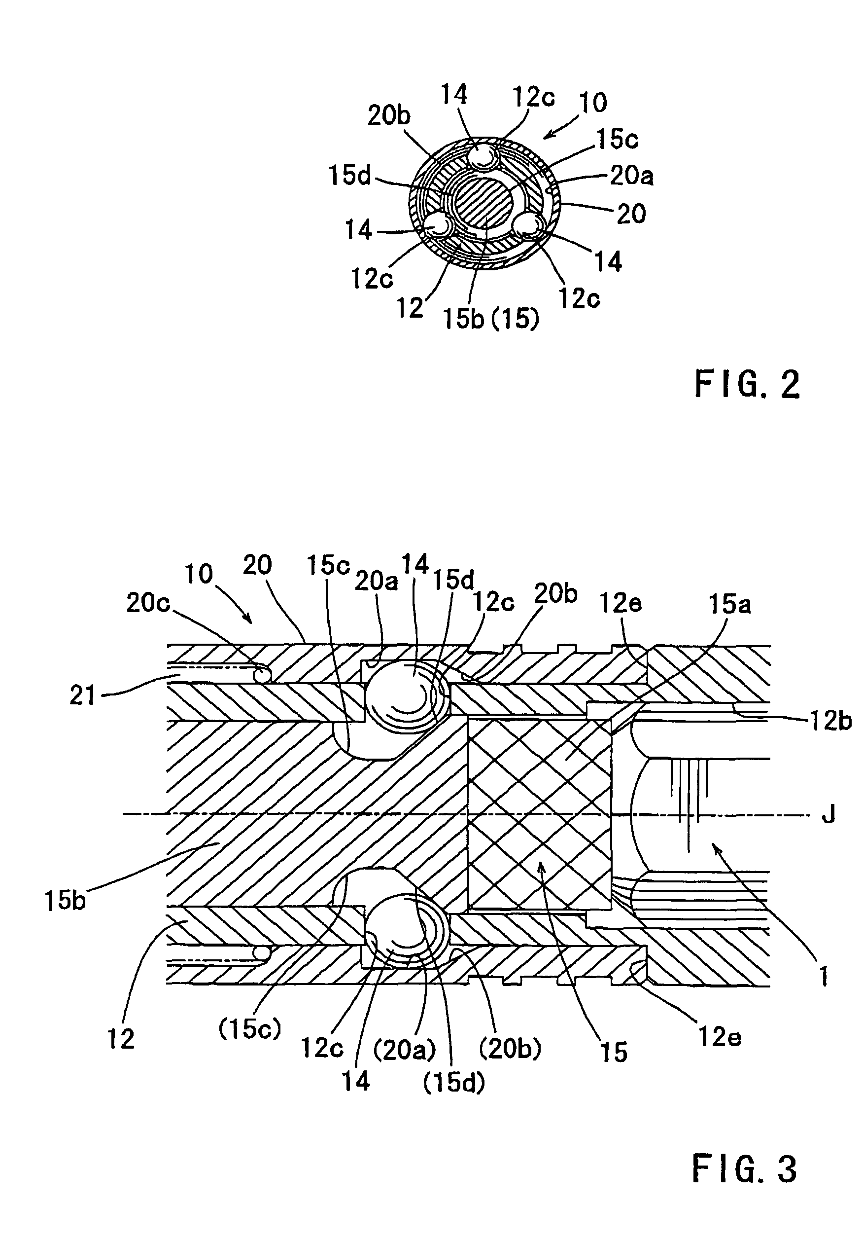
Image

Examples
Embodiment Construction
[0023]Each of the additional features and teachings disclosed above and below may be utilized separately or in conjunction with other features and teachings to provide improved bit mounting devices. Representative examples of the present invention, which examples utilize many of these additional features and teachings both separately and in conjunction with one another, will now be described in detail with reference to the attached drawings. This detailed description is merely intended to teach a person of skill in the art further details for practicing preferred aspects of the present teachings and is not intended to limit the scope of the invention. Only the claims define the scope of the claimed invention. Therefore, combinations of features and steps disclosed in the following detailed description may not be necessary to practice the invention in the broadest sense, and are instead taught merely to particularly describe representative examples of the invention. Moreover, various...
PUM
 Abstract
Description
Claims
Application Information