Self-moving device for movable furniture parts

a self-moving and furniture technology, applied in the direction of furniture parts, household applications, drawers, etc., can solve the problems of increasing the assembly cost and not being convenient for the end user to adjust the two different devices, and achieve the effect of cost-effective assembly

Active Publication Date: 2012-05-08
KING SLIDE WORKS CO LTD
View PDF29 Cites 104 Cited by
  • Summary
  • Abstract
  • Description
  • Claims
  • Application Information

AI Technical Summary

Benefits of technology

[0024]It is the primary object of the present invention to provide a self-moving device for movable furniture parts, which has an integrity and common of the parts and is cost-effective for assembly.

Problems solved by technology

Therefore, it is necessary to install two devices for a drawer to be self-opening and self-closing, which increases the cost of assembly.
In addition, it is not convenient for the end user to adjust the two different devices.

Method used


Image

  • Self-moving device for movable furniture parts
  • Self-moving device for movable furniture parts
  • Self-moving device for movable furniture parts

Examples


Embodiment Construction

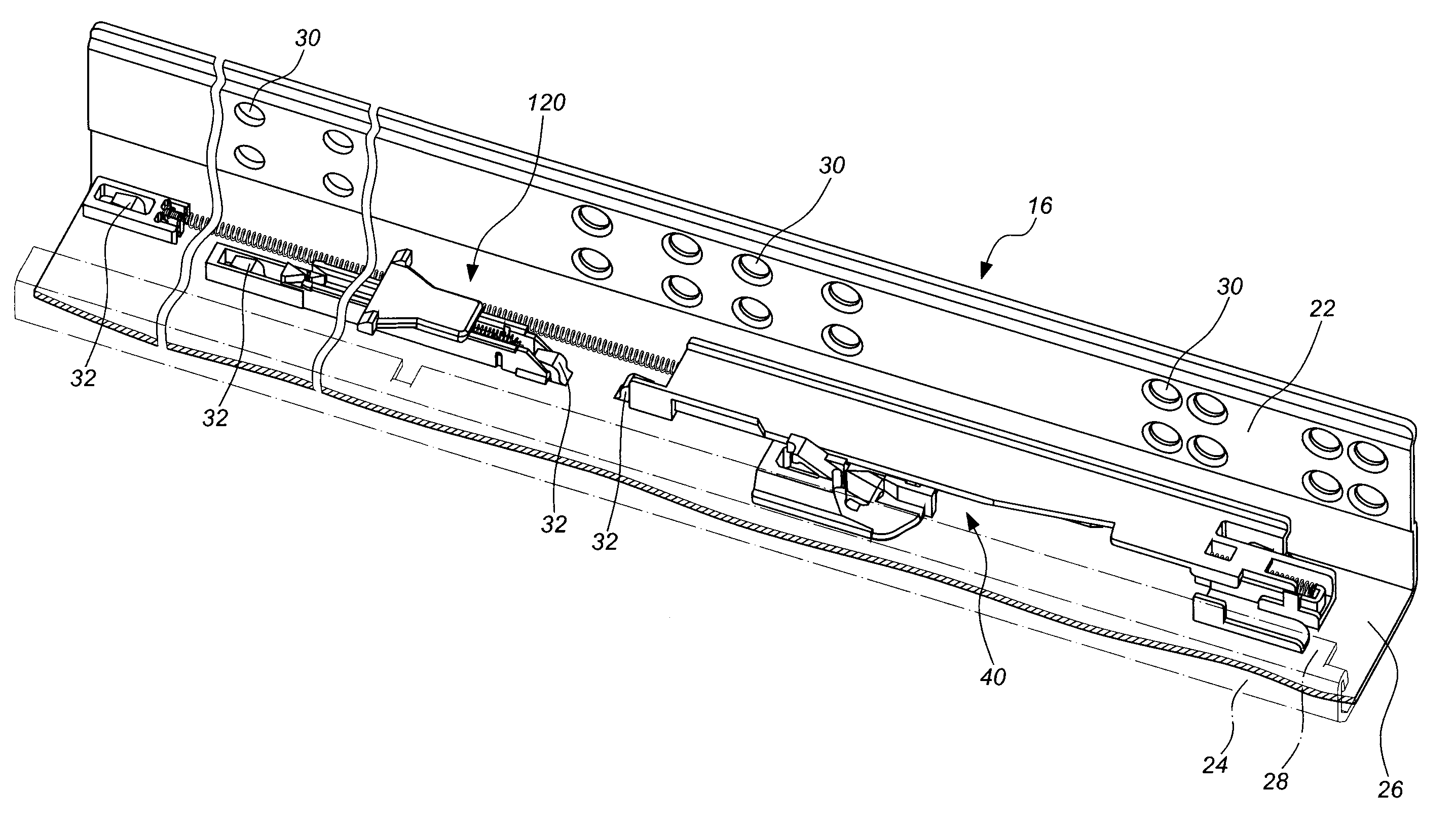
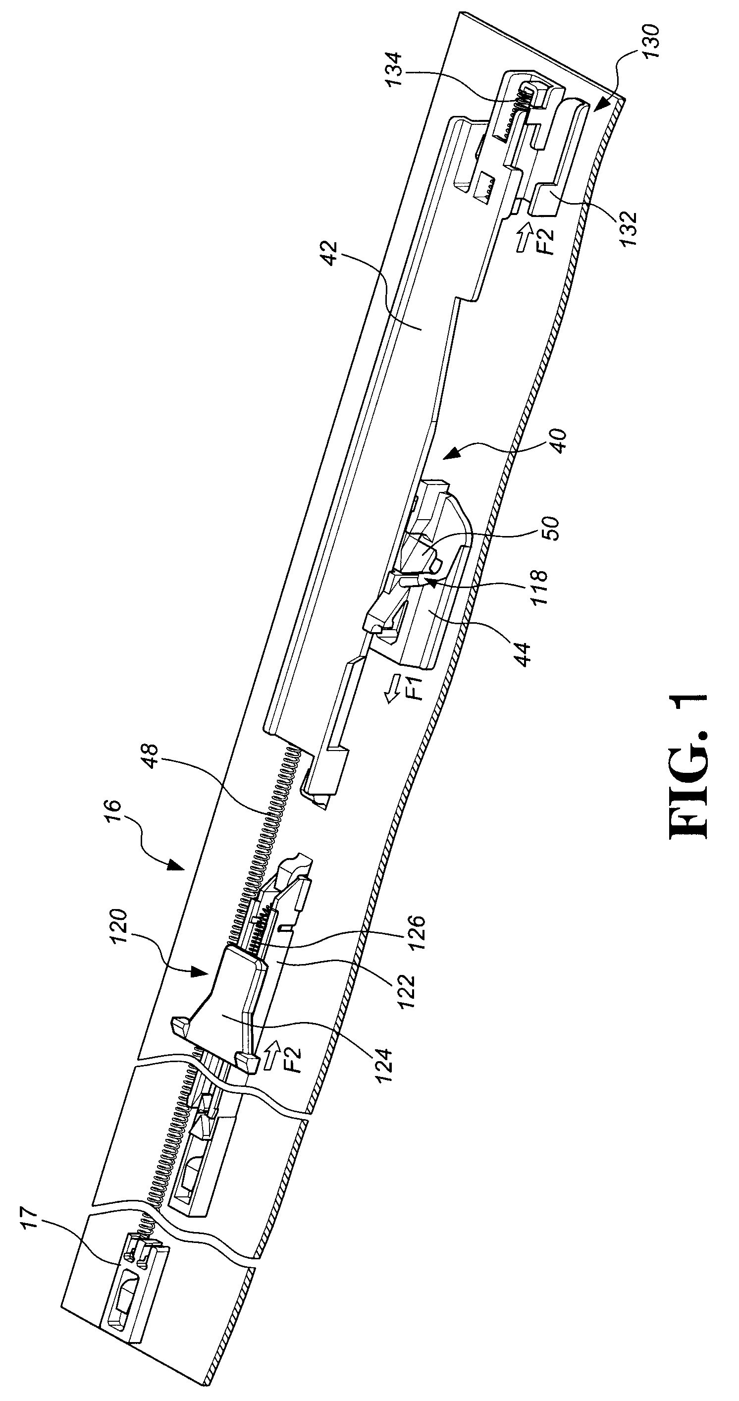
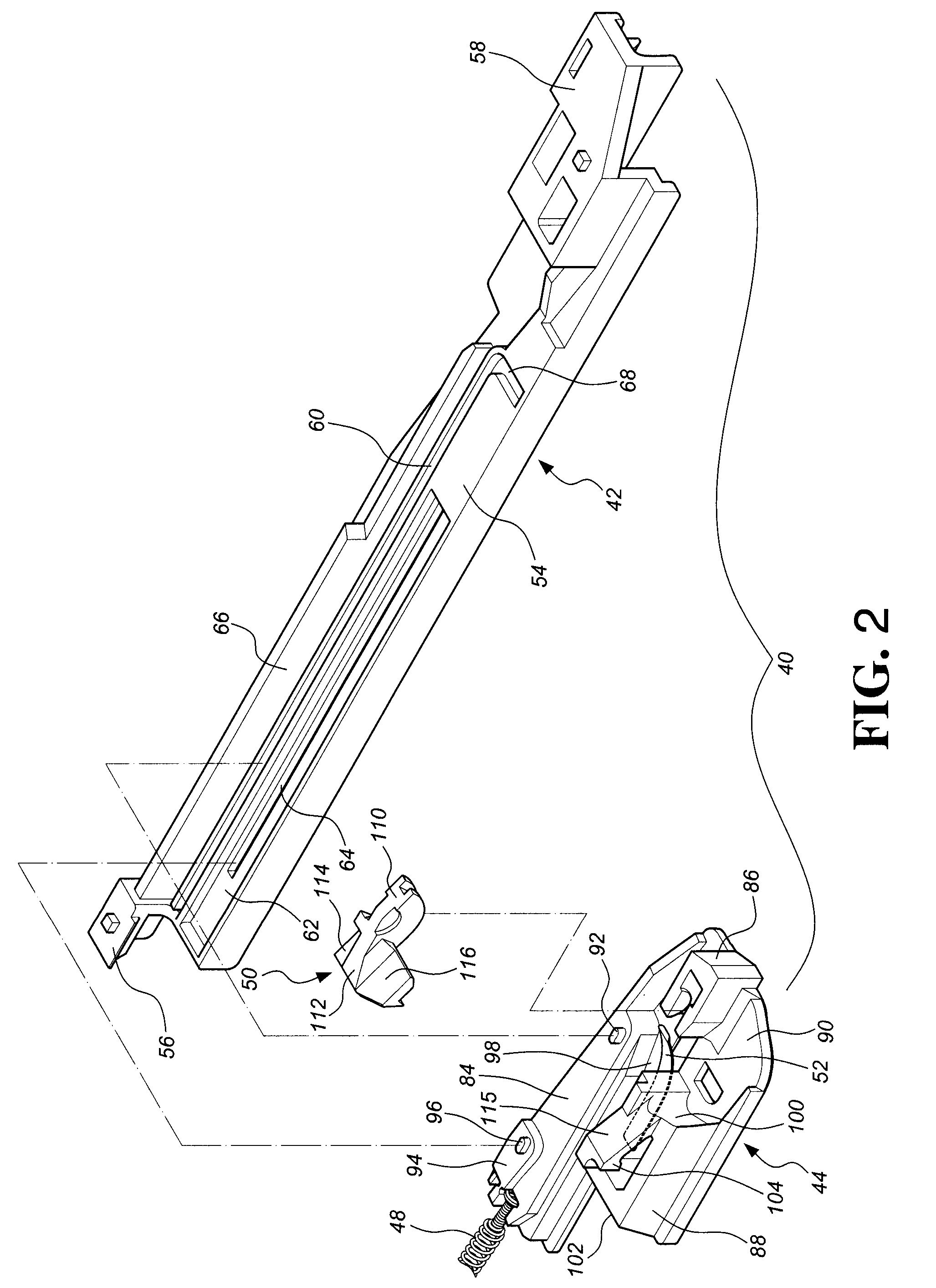
[0055]A self-moving device for movable furniture parts of the present invention, as shown in FIG. 1, comprises a stationary part 16 which may a part of a cabinet or a stationary rail of a slide assembly. In this embodiment, the present invention comprises a closing mechanism 40 mounted on the stationary part 16. The closing mechanism 40 comprises a guiding member 42 fixed on the stationary part 16, a slide base 44 movably connected to the guiding member 42, and a first elastic member 48 disposed on the stationary part 16. The first elastic member 48 is connected between the slide base 44 and the stationary part 16. The first elastic member 48 provides an elastic force to act on the slide base 44. In a preferred embodiment, a connecting seat 17 is fixed on the stationary part 16 and connected with the first elastic member 48 so as to keep the slide base 44 to move towards a first direction F1 constantly. A locking member 50 is connected to the slide base 44 and located between the sl...


PUM


Abstract

A self-moving device for movable furniture parts includes a movable part which is movable with respect to a stationary part. The movable part includes first and second connecting portions. A closing mechanism includes a slide base which is movable in response to a force generated by a first elastic member. A locking member connected to the slide base is adapted to engage with the first connecting portion so that the movable part is urged by the first elastic member to be self-closing with respect to the stationary part. An opening mechanism includes a push member urged by a second elastic member to act on the second connecting portion. The movable part may be pushed by an external force to disengage the locking member from the first connecting portion so that the movable part is urged by the second elastic member to be self-opening with respect to the stationary part.

Description

BACKGROUND OF THE INVENTION[0001]1. Field of the Invention[0002]The present invention relates to a self-moving device for movable furniture parts, in particular to a device that is self-closing and self-opening to control a movable part of a piece of furniture.[0003]2. Description of the Prior Art[0004]There are quite a few drawers having a self-opening function, which uses a restoring force to push a drawer in an open status when the drawer is released from its retaining situation. This device is designed only for opening the drawer, such as U.S. Pat. No. 5,040,833 to Brunnert, titled “Closing Device for Drawers”; U.S. Pat. No. 7,347,515 to Lu, titled “Sliding Rail Assembly Auto Opening Mechanism for Drawer”; U.S. Pat. No. 7,374,261 to Wang, titled “Push-Open Type Slide Structure”; U.S. Pat. No. 7,413,270 to Chang et al., titled “Locking Device of Sliding Drawer; and European Patent No. EP 0743032 B1 titled “Drawer Slide”.[0005]Another device is designed only for closing the drawer...

Claims


Application Information

Patent Timeline
Patent Type & Authority Patents(United States)
IPC IPC(8): A47B88/00
CPCA47B88/0481A47B2210/0094A47B88/47
Inventor LIANG, HSIU-CHIANGCHEN, KEN-CHINGWANG, CHUN-CHIANG
Owner KING SLIDE WORKS CO LTD
Why Eureka
Try Eureka