Anti-resonant circuit arrangement

a technology of anti-resonant circuit and antenna wiring, which is applied in the direction of transmission, support structure mounting, antennas, etc., can solve the problems of comparatively delicate and easily damaged, comparatively costly to produce or mount, and relatively expensive to produce anti-resonant circuit arrangements. , to achieve the effect of high degree of dependability of the operation of the anti-resonant circuit assembly and cost-effective assembly

Active Publication Date: 2008-12-23
MD ELEKTRONIK
View PDF18 Cites 1 Cited by
  • Summary
  • Abstract
  • Description
  • Claims
  • Application Information

AI Technical Summary

Benefits of technology

[0010]The present invention is therefore based in part on the object of creating an anti-resonant circuit arrangement with a housing of the type mentioned at the outset, which avoids the mentioned disadvantages and in particular permits a cost-effective assembly, or a technically simple fitting together. It is moreover intended to achieve a high degree of dependability of the operation of the anti-resonant circuit assembly.

Problems solved by technology

This arrangement has the disadvantage, inter alia, that it is comparatively delicate and can be easily damaged in the course of further production steps, for example.
Such an anti-resonant circuit arrangement is relatively costly to produce.
The embodiments of anti-resonant circuit arrangements with a choke and a capacitor so far known, in particular those which are employed in motor vehicles, inter alia have the disadvantage that they are comparatively costly to produce or mount, or that their mechanical structure, or the electrical contact elements, are susceptible to external interference.

Method used


Image

  • Anti-resonant circuit arrangement
  • Anti-resonant circuit arrangement
  • Anti-resonant circuit arrangement

Examples


Embodiment Construction

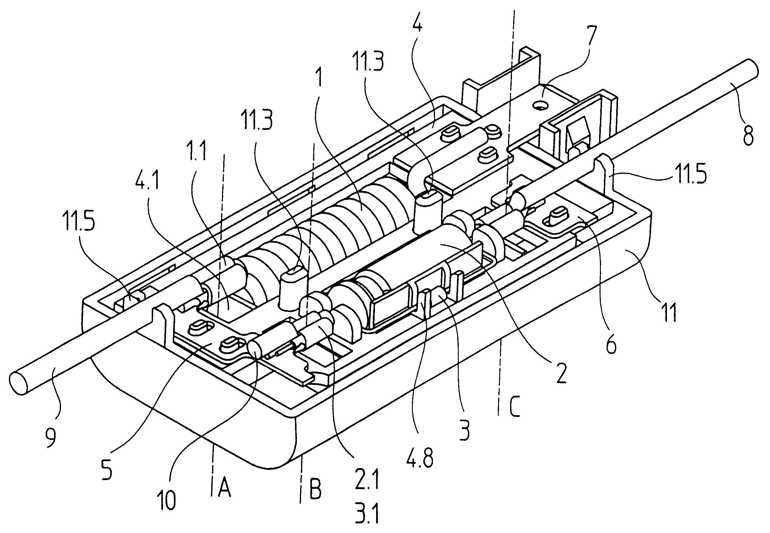
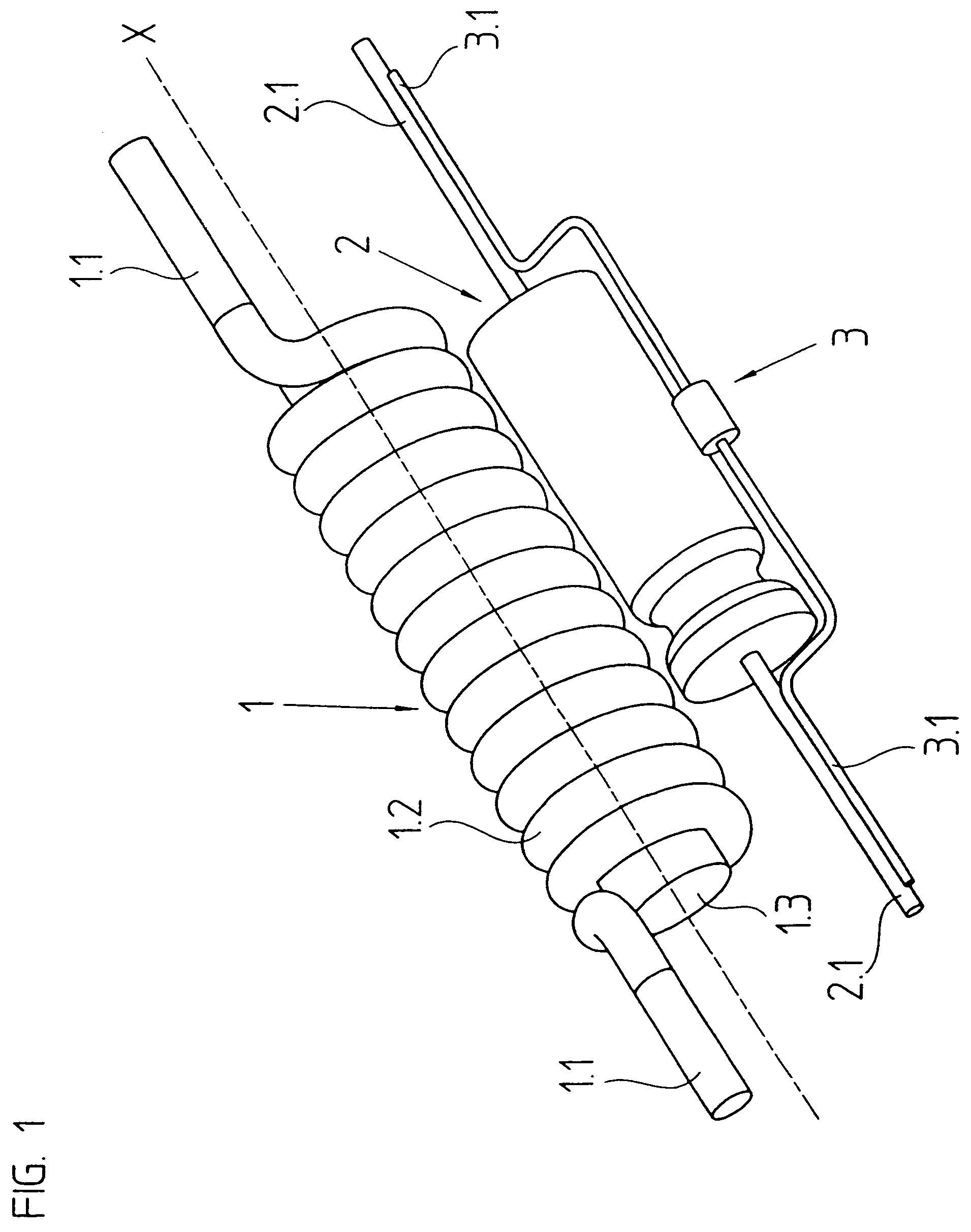
[0028]The electrical components of the anti-resonant circuit arrangement in accordance with the exemplary embodiment are represented in FIG. 1.

[0029]Inter alia, FIG. 1 shows a plan view of a choke 1, such as is employed in the represented exemplary embodiment of an anti-resonant circuit arrangement in an antenna wiring system of a motor vehicle. The choke 1 includes a copper wire provided with an insulating lacquer, which has been bent around the central axis X along a cylindrical helical line in a large area of the choke 1, so that the windings 1.2 of the choke 1 are helically designed, or the wound area has a helical shape. The windings 1.2 enclose a cylindrical iron core 1.3 and are glued to it for mechanical fixation in place. Furthermore, in accordance with FIG. 1 the choke 1 has two connecting areas 1.1, in which the insulating lacquer has been removed from the copper wire.

[0030]The anti-resonant circuit arrangement in accordance with FIG. 1 includes a first capacitor as a fur...


PUM


Abstract

An anti-resonant circuit arrangement for an antenna wiring system, the anti-resonant circuit arrangement including a first electrical component having a connecting area and a second electrical component, wherein the first and second electrical components combine to produce an anti-resonance effect. An electrical conductor that contacts said connecting area and a support plate having an opening that defines a geometric surface, wherein the connecting area is arranged so that a straight line is defined which is orthogonal to and penetrates the geometrical surface and intersects the connecting area.

Description

RELATED APPLICATION[0001]Applicants claim, under 35 U.S.C. §119, the benefit of priority of the filing date of Jan. 14, 2004 of a German patent application, copy attached, Serial Number 10 2004 001 899.5, filed on the aforementioned date, the entire contents of which is incorporated herein by reference.BACKGROUND OF THE INVENTION[0002]1. Field of the Invention[0003]The present invention relates to an anti-resonant circuit arrangement for an antenna wiring system, having at least two electrical components, namely a choke and at least one capacitor, which is particularly suitable for being installed in motor vehicles.[0004]2. Discussion of Related Art[0005]Wires for heating rear windows of modern motor vehicles are quite often simultaneously used as an antenna for receiving high-frequency signals. So that switch-on pulses of the rear window heater, for example, do not interfere with the received signals, chokes or inductors of appropriate inductivity and capacitors are often installed...

Claims


Application Information

Patent Timeline
Patent Type & Authority Patents(United States)
IPC IPC(8): H01Q1/00H01Q1/32H01R4/18H05K5/00H05K7/02H05K7/14
CPCH05K7/02H01R4/18
Inventor MAYR, JOSEFFRIESE, NORBERT
Owner MD ELEKTRONIK
Why Eureka
Try Eureka