Retaining element for a control device of an exhaust gas turbocharger

a technology of control device and control element, which is applied in the direction of threaded fasteners, rod connections, fastening means, etc., can solve the problems of inconvenient assembly of retaining elements, inability to meet the specific requirements of electrical control devices, and high production costs of such devices, so as to reduce assembly costs

Inactive Publication Date: 2018-12-06
IHI CHARGING SYST INT
View PDF0 Cites 1 Cited by
  • Summary
  • Abstract
  • Description
  • Claims
  • Application Information

AI Technical Summary

Benefits of technology

[0008]The advantage resides in the fact that no relative movement is possible between the first element portion and the second element portion and the connecting element simultaneously has a secure frictional and interlocking connection to the control rod. Therefore, the connecting element can be used both in pneumatic and electrical control devices. Furthermore, a substantially simpler and thus more cost-effective assembly is achieved.
[0009]In one embodiment, the first receiving element is designed in the form of a first passage opening and the second receiving element is designed in the form of a second passage opening. Since the receiving element is designed for fastening the control or movement device as passage openings, the connecting element can be produced cost-effectively by reason of its simple form. A further advantage is a saving on a securing element, as designed e.g. as a nut.
[0010]In a further embodiment of the connecting element in accordance with the invention, the first receiving element is designed for frictional and interlocking connection to a control rod of the control device. With the aid of the frictional and interlocking connection, a specific length of the movement device can be adjusted in a simple manner. A substantial advantage is a simple compensation of production tolerances which typically occur. Compensation is effected by simple rotation of the connecting element.
[0013]In a further embodiment, the connecting element has an attachment which is formed coaxially with the first receiving element. With the aid of this attachment, the frictional and interlocking connection e.g. in the form of a screw connection can be large enough even in a cost-effective design of the connecting element consisting of a thin metal sheet. Preferably, the attachment is formed on a first surface of the first element portion facing the second element portion because this region is easily accessible during assembly. A further advantage of this embodiment is the formation of a planar bearing surface for the securing element, preferably in the form of a nut.
[0015]In a further embodiment of the connecting element in accordance with the invention, a first element portion which is the first receiving element is designed for receiving standardized fixed or flat spanners. Therefore, during assembly of the connecting element, no tools which have to be specifically produced are required because typically standardised tools can be used, thus reducing assembly costs.

Problems solved by technology

By reason of this two-part design, this retaining element is not suitable in particular for electrical control devices.
Furthermore, the production thereof is costly in particular by reason of nut elements formed on both element parts.

Method used


Image

  • Retaining element for a control device of an exhaust gas turbocharger
  • Retaining element for a control device of an exhaust gas turbocharger

Examples


Embodiment Construction

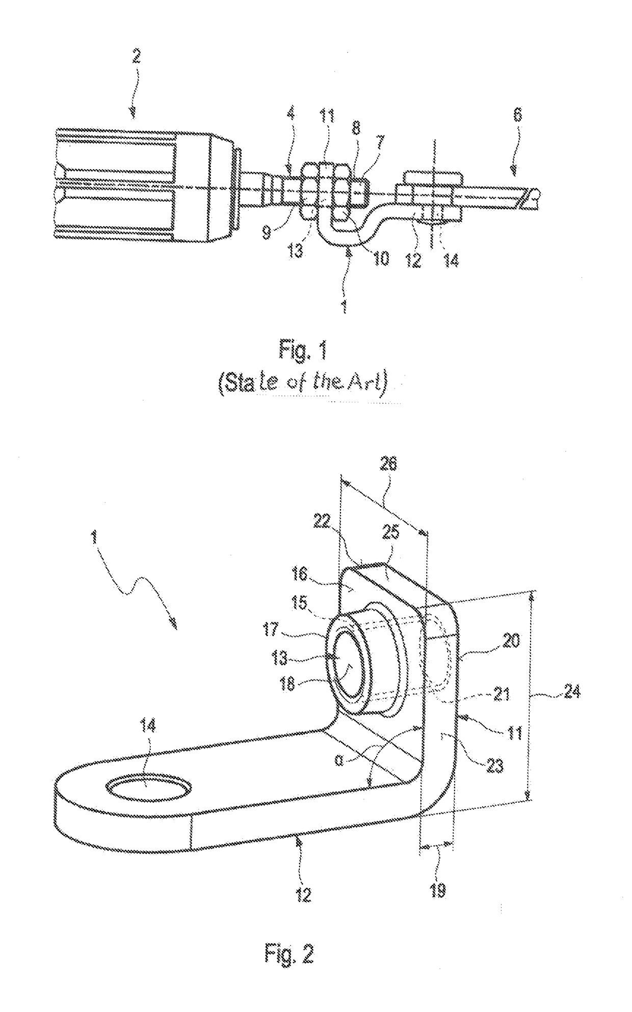
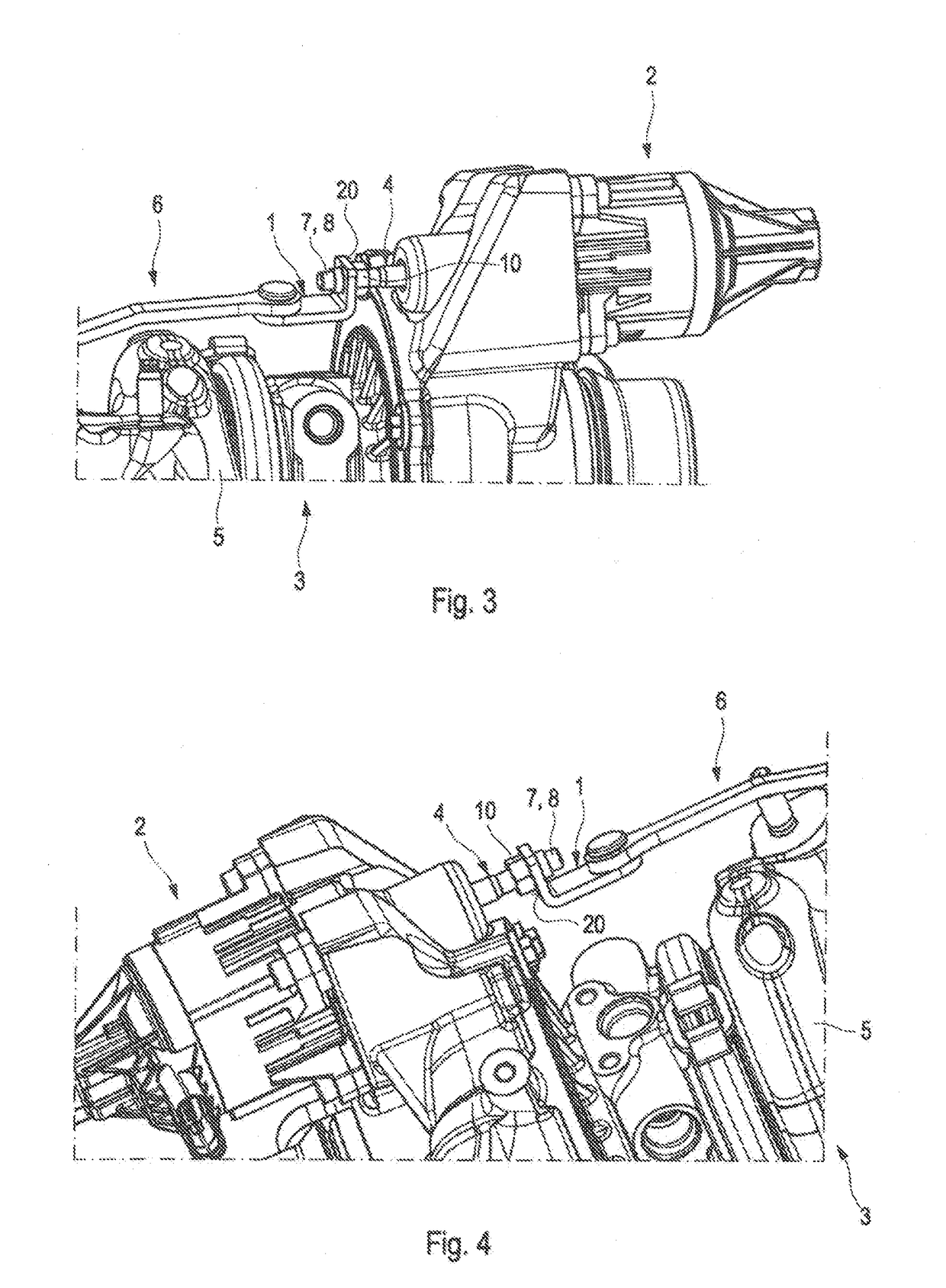
[0021]A connecting element 1 for a control device 2 of an exhaust turbocharger 3 according to a further prior art example is designed as shown in FIG. 1. The connecting element 1 serves to connect a control rod 4 of the control device 2 to a valve, not illustrated in greater detail, which is movably received in an exhaust gas conducting section 5 of the exhaust turbocharger 3. The valve is provided for opening and closing a flow deflection duct, not illustrated in greater detail, of the exhaust gas conducting section 5. With the aid of the flow deflection duct, gas which flows through the exhaust gas conducting section 5, typically exhaust gas of an internal combustion engine, not illustrated in greater detail, can be directed past a turbine wheel of the exhaust turbocharger 3. Such exhaust turbochargers 3 are adequately known and therefore shall not be explained in greater detail at this juncture.

[0022]In order to move the valve, it is connected to a corresponding movement device 6...


PUM


Abstract

In a connecting element for a control device of an exhaust turbocharger which connecting element comprises a first element portion having a first passage opening a second element portion having a second passage opening, the first passage opening serves to connect the connecting element to the control device and the second passage opening serves to connect the connecting element to a movement device.

Description

[0001]This is a continuation-in part application of pending international patent application PCT / EP2017 / 000180 filed 2017 Feb. 9 and claiming the priority of German patent application 10 2016 103 114.3 filed 2016 Feb. 23.BACKGROUND OF THE INVENTION[0002]The invention relates to a retaining element for a control device of an exhaust turbocharger.[0003]Exhaust turbochargers are known. They serve to increase the efficiency of internal combustion engines, to which they are thermodynamically and mechanically connected. In order to improve the operating behavior of the internal combustion engine and of the exhaust turbocharger, the exhaust turbocharger has a control device, by means of which an exhaust gas quantity flowing onto a turbine wheel of the exhaust turbocharger can be regulated. This control device can be designed in the form of a so-called waste gate, which has a bypass duct that can be opened and closed with the aid of a valve, or it can be designed in the form of an adjusting...

Claims


Application Information

Patent Timeline
Patent Type & Authority Applications(United States)
IPC IPC(8): F02B37/18F16B37/02F16B7/18
CPCF02B37/186F16B37/02F16B7/182Y02T10/12
Inventor JAENIKE, LORENZNUSSHAG, DIRKWIDENMAIER, ANGELINADICK, VIKTORJUST, DANIEL
Owner IHI CHARGING SYST INT
Why Eureka
Try Eureka