
Baler with Improved Cross Member for Mounting the Gearbox

a cross member and gearbox technology, applied in the field of balers, can solve the problems of high local stress in the cross member and high construction cost, and achieve the effect of cost-effective construction

Active Publication Date: 2017-08-03
BLUE LEAF I P INC
View PDF0 Cites 1 Cited by
  • Summary
  • Abstract
  • Description
  • Claims
  • Application Information

AI Technical Summary

Benefits of technology

The present invention aims to provide a baler that can transfer the forces exerted on the gearbox to the frame in a cost-efficient way, while accommodating any misalignments. The invention allows for improved force transfer with reduced stress on the cross member, by using mounting brackets to handle misalignments and by optimizing the contact surface area between the cross member and the mounting brackets. Additionally, the invention provides a simplified shape for the cross member while efficient force transfer to the frame is achieved.

Problems solved by technology

In such an embodiment the assembly of the cross member and gearbox involve a lot of machining and welding, resulting in an expensive construction.
In prior art embodiments heavy loads on the gearbox are not dealt with in an optimal way, and may result in high local stresses in the cross member.

Method used


Image

  • Baler with Improved Cross Member for Mounting the Gearbox
  • Baler with Improved Cross Member for Mounting the Gearbox
  • Baler with Improved Cross Member for Mounting the Gearbox

Examples


first embodiment

[0041]Now a cross member 110 with corresponding mounting brackets 120 according to the invention will be illustrated referring to FIG. 3, FIG. 3A and FIG. 3B.

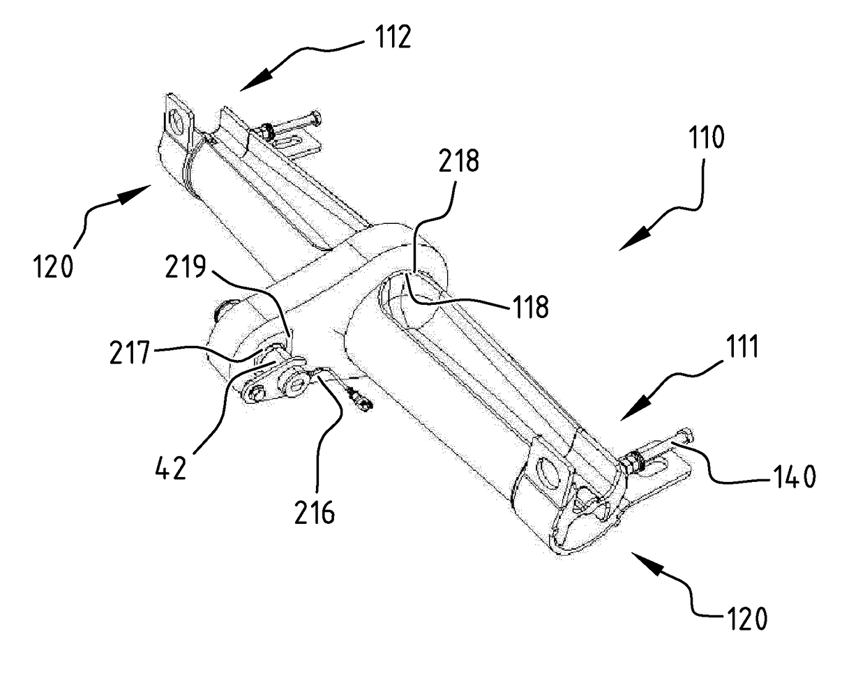
[0042]The cross member 110 has a first end 111 and a second end 112. The first end 111 and the second end 112 are received in a first and second mounting bracket 120, such that the first end and the second end of the cross member is coupled to the frame in a weld-free way. The mounting brackets 120 can be welded or otherwise fixed to the frame 11 of the baler 10. A top part 40 of a gearbox 21 is coupled to the cross member 110 between the first end 111 and the second end 112.

[0043]The first end 111 and the second end 112 comprise a part 113 having a circular cylindrical outer surface, wherein the axis of the cylindrical outer surface extends in the transverse direction of the baler. The radius R1, R2 may vary in the transverse direction, see FIG. 3B. Each mounting bracket 120 has an a cylindrical mounting surface 121, i.e. the ...

second embodiment

[0048]FIG. 4 illustrates a cross member 110 with corresponding mounting brackets 120. The cross member 110 has a first end 111 and a second end 112. The first end 111 and the second end 112 are received in a mounting bracket 120, such that the first end 111 and the second end 112 of the cross member is coupled to the frame in a weld-free way. Also, the connection is free from shear and friction force transferring bolts which extend vertically through the cross member. However, there may be provided a pushing member, such as a push bolt 140, which keeps the cross member 110 in place with its first and second ends 111, 112 received in first and second mounting brackets 120. Alternatively, there may be provided a pull member, such as a pull bolt (not shown), for maintaining in position the first and second ends 111, 112.

[0049]In the second embodiment a coupling flange 216 for coupling the cross member 110 to a gearbox is clamped on the cross member 110 in a weld-free manner. To that en...


PUM


Abstract

A baler having a longitudinal direction and a transverse direction. The baler includes a frame, a gearbox, and a cross member extending in the transverse direction for coupling a top part of the gearbox to the frame. The cross member has a first end coupled to the frame and a second end coupled to the frame. The top part is coupled to the cross member between the first end and the second end. The frame is provided with a first mounting bracket and a second mounting bracket adapted for receiving the first end and the second end, respectively, in a weld-free way.

Description

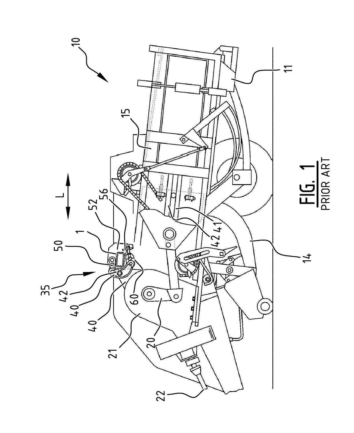
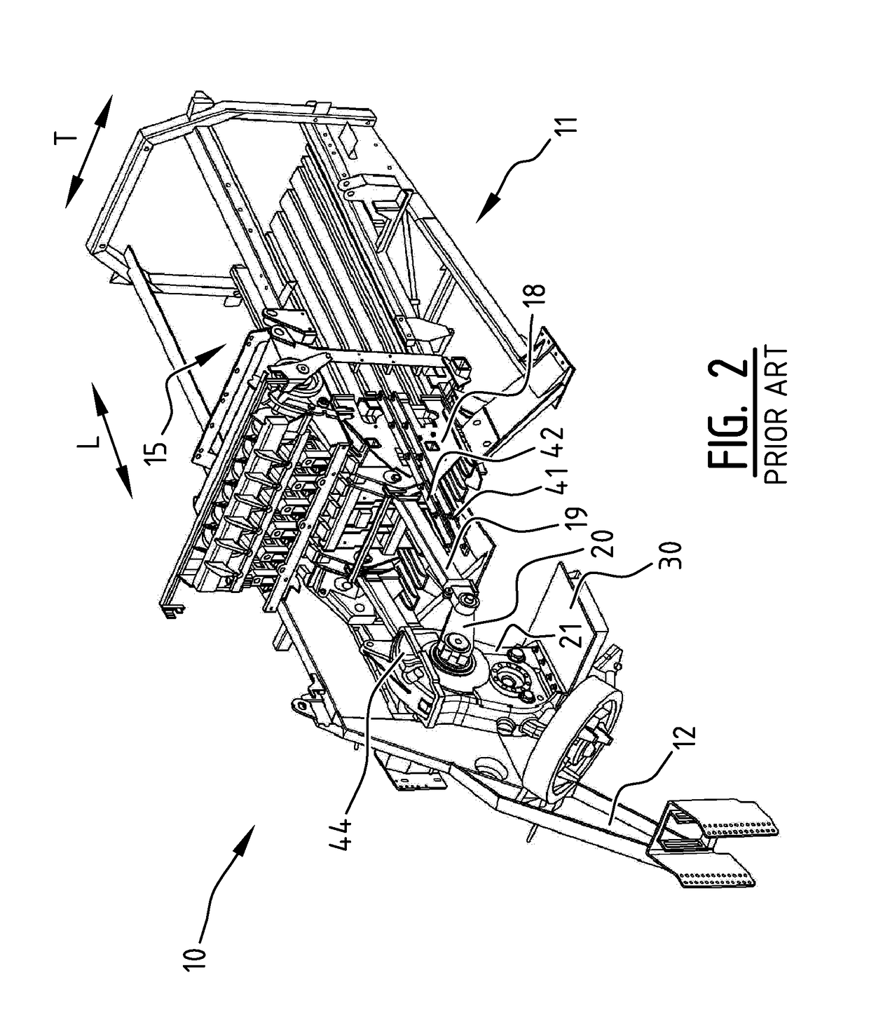
FIELD OF THE INVENTION[0001]The present invention relates to balers comprising a frame, a gearbox, and a cross member extending in the transverse direction for coupling a top part of the gearbox to the frame. More in particular the invention relates to rectangular balers provided with a heavy gearbox.BACKGROUND OF THE INVENTION[0002]In prior art balers a top fork-like part of the gearbox is connected via a pin to a coupling flange which is welded to a cross member extending in a transverse direction of the baler, and the cross member is welded to the frame of the baler. Such a prior art baler will be discussed in detail below with reference to FIG. 1 and FIG. 2.[0003]In such an embodiment the assembly of the cross member and gearbox involve a lot of machining and welding, resulting in an expensive construction. Misalignments in the transverse direction can be taken up by the parts during assembly.[0004]In prior art embodiments heavy loads on the gearbox are not dealt with in an opti...

Claims


Application Information

Patent Timeline
IPC IPC(8): A01F15/08
CPCA01F15/08A01F15/0841B30B9/306
Inventor DEMON, FREDERIKDELAERE, PATRICKBONTE, XAVIER G.J.M.
Owner BLUE LEAF I P INC
Learn More