Stop cap

a technology of stop cap and stop rod, which is applied in the direction of machine supports, vibration dampers, machine frames, etc., can solve the problems of increased production costs of vibration dampers and complex assembly processes, and achieve the effect of ensuring the relative position of the protective elemen

Active Publication Date: 2017-09-05
THYSSENKRUPP BILSTEIN
View PDF17 Cites 1 Cited by
  • Summary
  • Abstract
  • Description
  • Claims
  • Application Information

AI Technical Summary

Benefits of technology

[0003]A disadvantage in this known vibration damper is that the stop buffer, the protective tube and the end cap are to form a preassembled structural unit independent of the vibration damper. These components must thus be assembled to form a preassembled structural unit in a dedicated, separate working step, which requires a suitable tool in order to be able to achieve a uniform resilient deformation of the resilient segments of the end cap in order to be able to latch the protective tube with the end cap. In order to produce the positive-locking connection, a particular tool is thus required, which has to be separately obtained or produced. The assembly process is thus more complex and the production costs for the vibration damper are increased.
[0004]Exemplary embodiments of the present invention are directed to a vibration damper of the type mentioned in the introduction that can be assembled in a cost-effective manner by means of a simple assembly process.
[0007]In accordance with exemplary embodiments of the present invention, the cap comprises several spring tongues that are disposed distributed over the circumference of the cap. In a particularly preferred manner, three spring tongues are provided distributed at regular intervals over the circumference of the cap. This ensures a reliable positive-locking connection between the cap and the protective element.
[0009]In an advantageous manner, the cap comprises a stop surface for positioning the protective element by means of which the protective element can be positioned relative to the positive-locking element in a position suitable for forming the positive-locking connection. The protective element lies against the stop surface in the assembled position. The stop surface is disposed on the cap such that a receptacle, provided on the protective element, for the positive-locking element is positioned relative thereto such that the positive-locking element penetrates radially outwards into the receptacle by virtue of the spreading action of the spring tongue produced when the cap is assembled. In this manner, the protective element is readily aligned into the correct position for forming the positive-locking connection. In accordance with a preferred embodiment of the invention, the stop surface is formed as a circular ring-shaped surface in order to reliably and effectively position the protective element relative to the cap.

Problems solved by technology

A disadvantage in this known vibration damper is that the stop buffer, the protective tube and the end cap are to form a preassembled structural unit independent of the vibration damper.
The assembly process is thus more complex and the production costs for the vibration damper are increased.

Method used


Image

  • Stop cap
  • Stop cap
  • Stop cap

Examples


Embodiment Construction

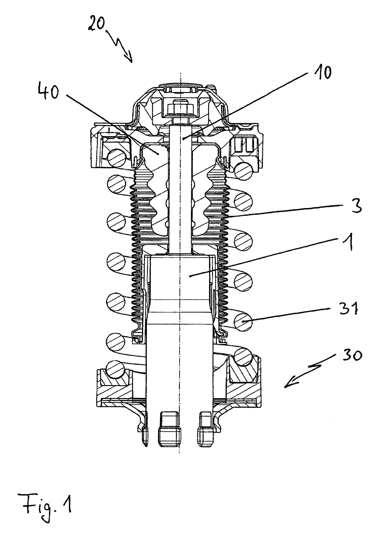
[0014]FIG. 1 shows a vibration damper having a cap in accordance with the invention, which is assembled onto one end of the damper tube 1 of the vibration damper. A piston rod 10 exits from the damper tube 1. The piston rod 10 is guided so as to be movable in an oscillating and reciprocating fashion in a sealing and guiding assembly which is not shown in FIG. 1 and is disposed on the piston rod exit-side end of the damper tube 1. With its end remote from the damper tube 1, the piston rod 10 is fixedly connected to a damper bearing assembly 20. The damper bearing assembly 20 will hereinafter be abbreviated to “damper bearing 20”. The damper bearing 20 is fixedly connected to a vehicle body of a motor vehicle which is not shown.

[0015]The damper tube 1 supports a spring plate 30 on which a spring end of a vehicle bearing spring 31 is supported. The other end of the vehicle bearing spring 31 is supported on the damper bearing 20.

[0016]The piston rod 10 is protected against surface damag...


PUM


Abstract

A cap for mounting on a damper tube of a vibration damper, having an outer shell region that is cylindrical at least in sections and at least one elastic spring tongue. At least one positively locking element is arranged on the spring tongue in order to produce a positively locking connection between the cap and a protective element of the vibration damper. The at least one spring tongue has a region which, in the non-mounted state of the cap, is set back inwardly in the radial direction with respect to the outer shell region. The set-back region has a spreading element, by way of which the spring tongue is spread outwardly in the radial direction during the mounting of the cap.

Description

BACKGROUND AND SUMMARY OF THE INVENTION[0001]The invention relates to a cap for assembly onto a damper tube of a vibration damper, having an outer peripheral region which is cylindrical at least in sections, and at least one resilient spring tongue, wherein disposed on the spring tongue is at least one positive-locking element for producing a positive-locking connection between the cap and a protective element of the vibration damper.[0002]German Patent Document DE 101 22 796 B4 discloses such a cap. The vibration damper described in this document includes a container tube in which a piston rod is guided in an axially movable manner, said piston rod being at least partially covered by a protective tube having at least one resilient fold. A stop buffer is disposed concentrically with respect to the piston rod, the stop buffer comes to lie against an end cap in an end region of a retracting movement of the piston rod. The end cap lies against the container tube in a completely assembl...

Claims


Application Information

Patent Timeline
Patent Type & Authority Patents(United States)
IPC IPC(8): F16F5/00F16F9/32F16F9/38F16F9/04
CPCF16F9/3242F16F9/38
Inventor MRUGALLA, DAMIANSCHRICHTEN, MARKUS
Owner THYSSENKRUPP BILSTEIN
Why Eureka
Try Eureka