Bearing isolator

Active Publication Date: 2018-06-07
AES ENG
View PDF5 Cites 1 Cited by
  • Summary
  • Abstract
  • Description
  • Claims
  • Application Information

AI Technical Summary

Benefits of technology

[0016]Preferably, filaments are bundled together in a brush located within a retaining orifice. Such an a

Problems solved by technology

The increasing use of variable frequency drives (VFDs) within the electric motor industry as a consequence of energy conservation targets has caused a significant increase in stray voltage accumulation within shafts of rotating machinery.
Once the build

Method used


Image

  • Bearing isolator
  • Bearing isolator
  • Bearing isolator

Examples


Embodiment Construction

[0028]The invention will now be described, by way of example only, with reference to the accompanying drawings.

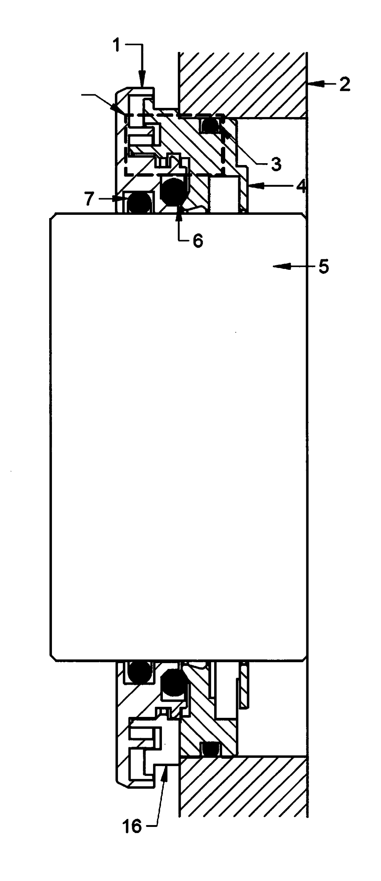
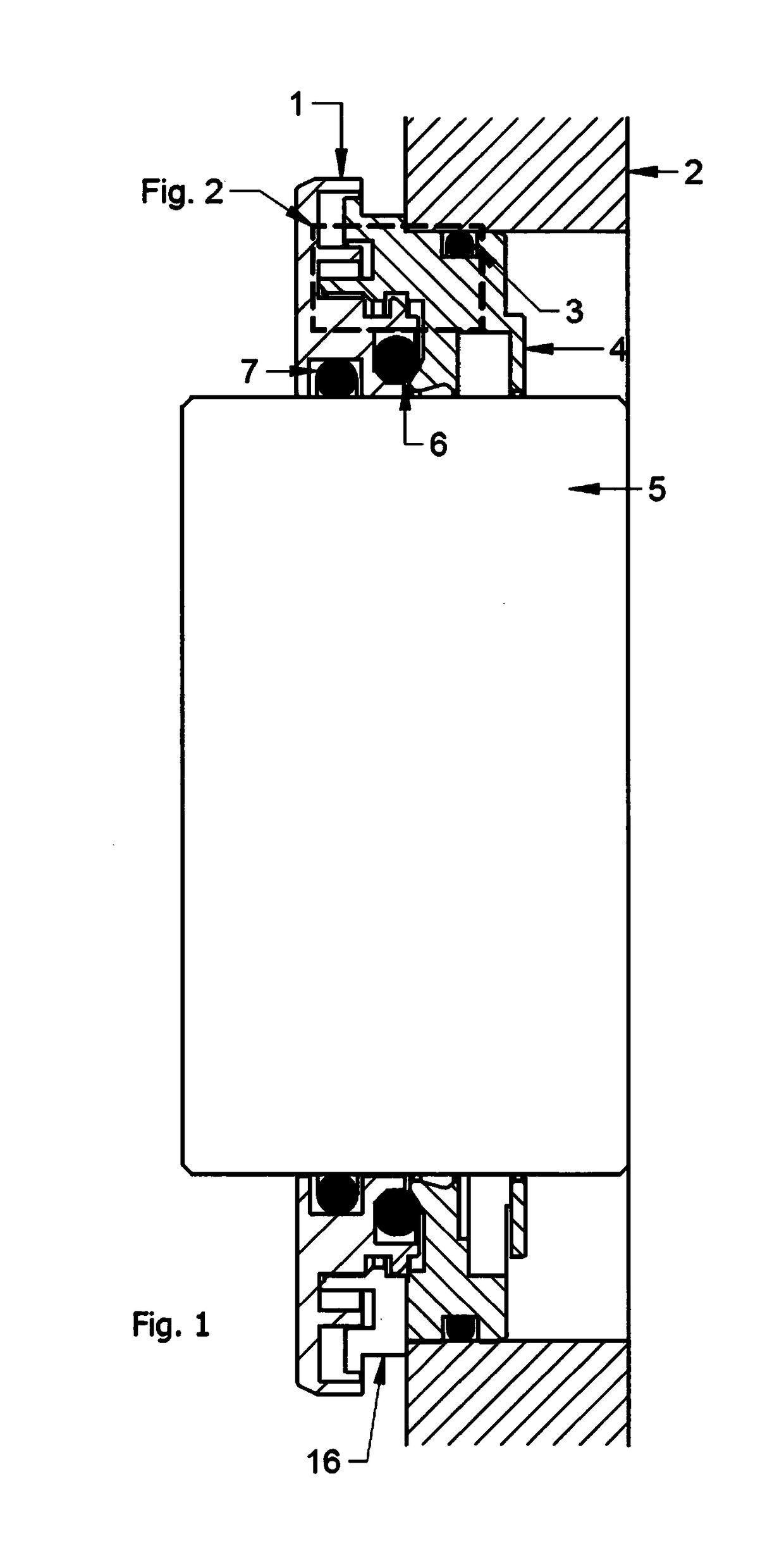
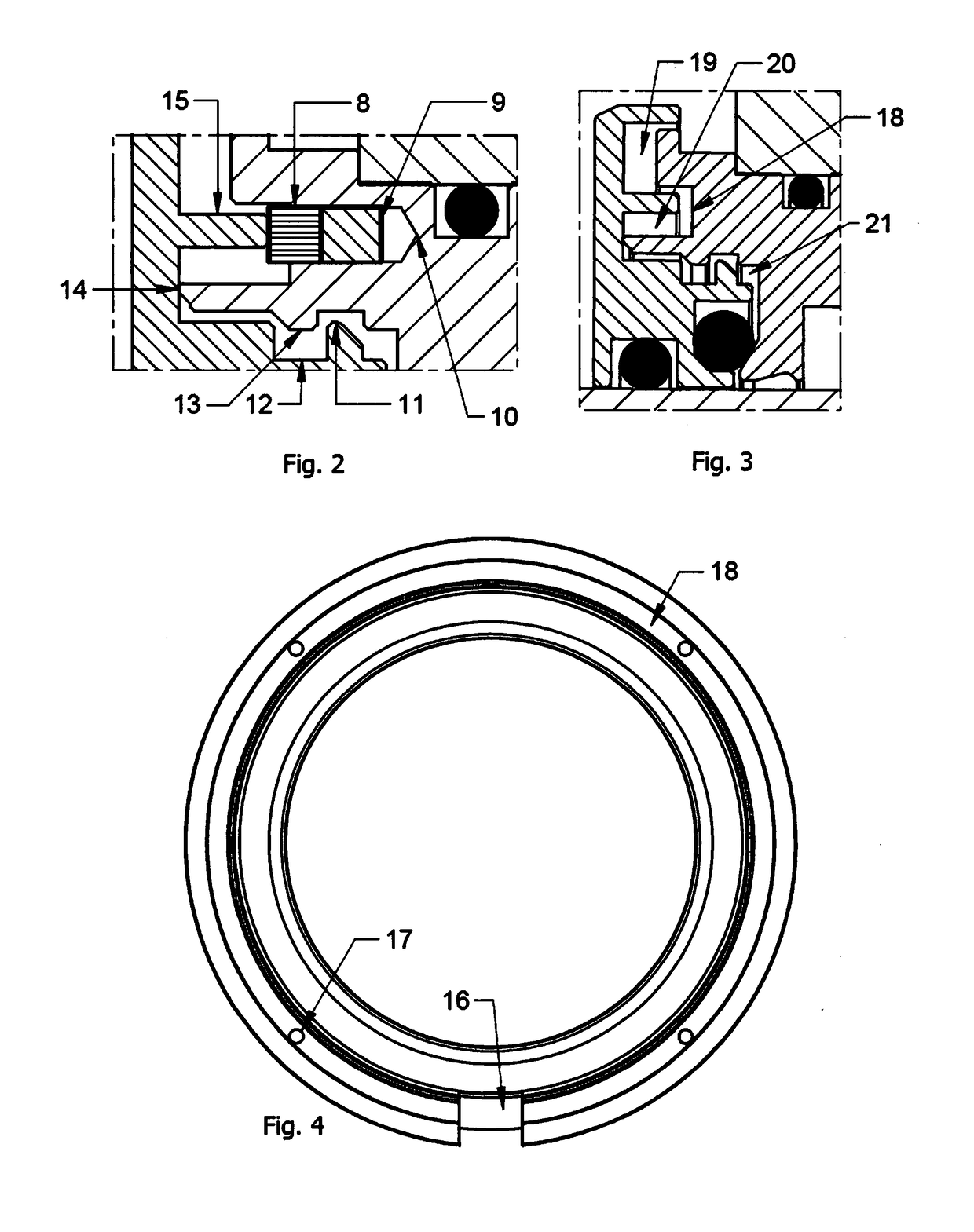
[0029]Referring to FIGS. 1 to 3 of the accompanying drawings, there is shown the stationary component 4 of a grounding labyrinth bearing protector which is located centrically around a shaft 5 and is a press fit into housing 2. A stationary o ring 3 aids in the fitment of the stationary component into the bore defined by the housing 2 and shaft 5. The rotational component 1 of the bearing protector is secured relative to the shaft 5 via a conductive rotary o ring 7. A tortuous or arduous path is formed between the stationary and rotational components, this path including gaps 19, 20 and 21 between the components. Also in the flow[path is a dynamic o ring 6 which, when the shaft 5 is stationary, completely seals the bearing chamber from atmosphere. During rotation of shaft 5, o ring 6 lifts allowing the bearing chamber to breath and expel air.

[0030]The stationary component 4...


PUM


Abstract

A bearing isolator apparatus is for use in a piece of equipment which includes a rotatable shaft and a housing through which the shaft extends. The apparatus includes a static component for securing to the housing and a rotational component for securing to the shaft. A tortuous fluid path extends between the static component and the rotational component and a plurality of electrically conductive filaments extends between the static component and the rotational component, such that an electrical current can pass between the components. One or more conductive members electrically connect the rotor to the shaft.

Description

FIELD OF THE INVENTION[0001]The present invention relates to bearing isolators and more particularly to electrical charge dissipating devices for rotating machinery. The invention is especially concerned with conductive labyrinth bearing protectors for directing electrostatic charge to ground.BACKGROUND TO THE INVENTION[0002]The increasing use of variable frequency drives (VFDs) within the electric motor industry as a consequence of energy conservation targets has caused a significant increase in stray voltage accumulation within shafts of rotating machinery.[0003]VFDs regulate the speed of the motor by converting alternating current (AC) voltage to direct current (DC) voltage, then back to a pulse width modulated AC voltage of variable frequency. The voltage change relative to the time induces a form of capacitance between the motor stator and the rotor, which in turn induces a voltage on the rotating shaft. Once this shaft voltage builds up it will divert to ground through the pat...

Claims


Application Information

Patent Timeline
IPC IPC(8): F16C33/72H02K11/40
CPCF16C33/723H02K11/40H02K5/10F16C33/72F16C2202/32H02K5/141
Inventor POGMORE, OLIVER
Owner AES ENG
Why Eureka
Try Eureka