Image display apparatus

a technology for displaying apparatus and earphones, which is applied in the manufacture/assembly of earpieces/earphones, television systems, instruments, etc., can solve the problems of losing secrecy, not being able to clearly hear sound in a noisy environment, and not being able to pull out earphones directly from the main body of the apparatus to insert them into ears

Inactive Publication Date: 2012-05-08
KONICA MINOLTA INC
View PDF21 Cites 69 Cited by
  • Summary
  • Abstract
  • Description
  • Claims
  • Application Information

AI Technical Summary

Problems solved by technology

However, the technology disclosed in Patent Document 1 does not allow pulling out the earphones from the main body of the apparatus to directly insert them into ears.
Consequently, it is not possible to clearly hear sound in a noisy environment.
Further, it causes problems of losing secrecy due to sound leakage and irritating others with discomfort.
Further, it is understood that it is difficult to surely locate earphones at the positions of ears, the positions of ears being different depending on wearers.
Still further, since the earphones cannot be attached to nor detached from the main body of the apparatus, it is understood that it is difficult to make the apparatus in a compact size so as to be put away.
In the technology disclosed by patent Document 2, since moving the speakers changes the head holding shape, it is understood that it is difficult to surely locate the earphones at the positions of ears, wherein the positions of ears are different depending on wearers.
Further, this may cause sound leakage, and accordingly secrecy may be lost.

Method used


Image

  • Image display apparatus
  • Image display apparatus
  • Image display apparatus

Examples


embodiment 1

[Embodiment 1]

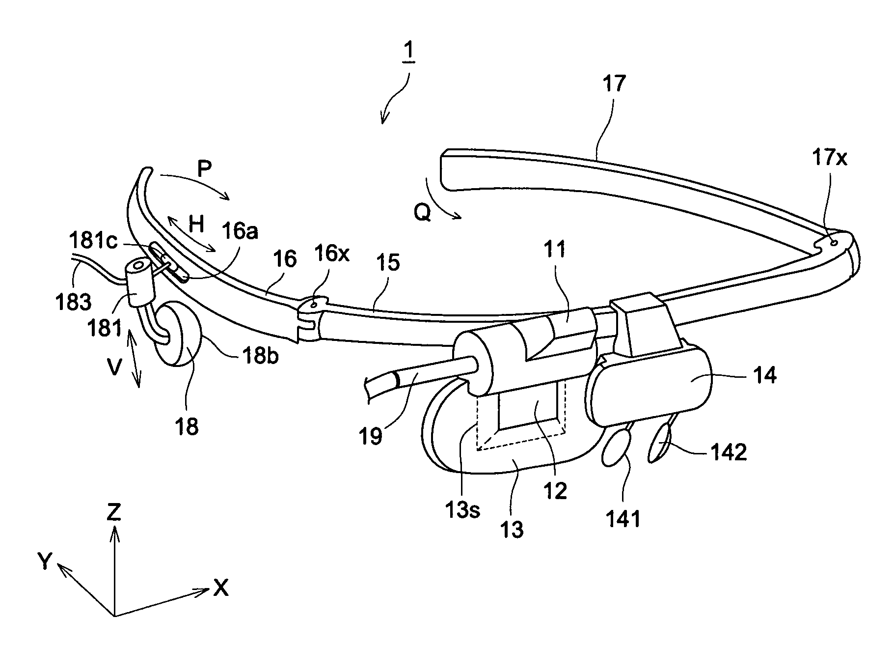
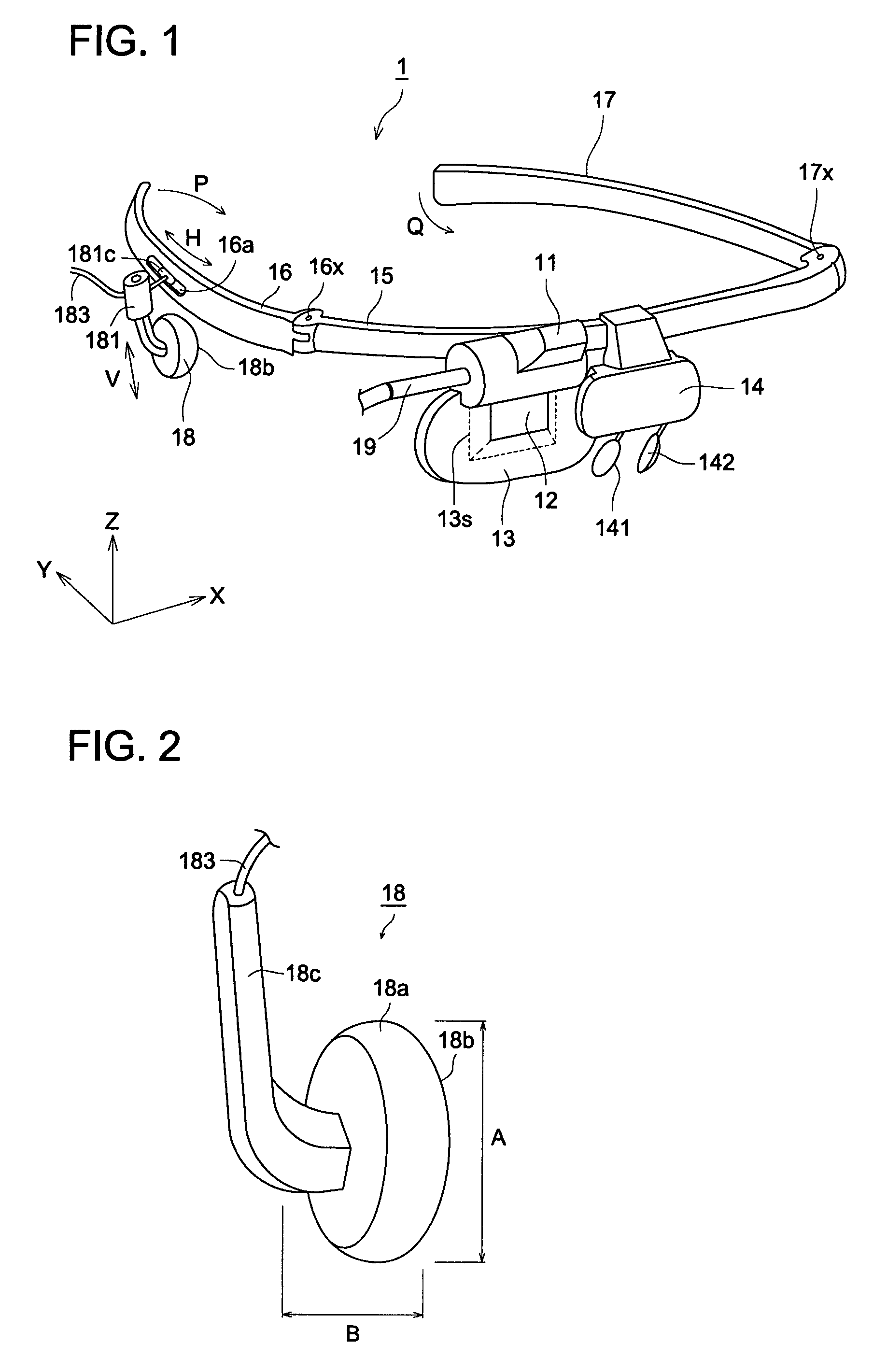
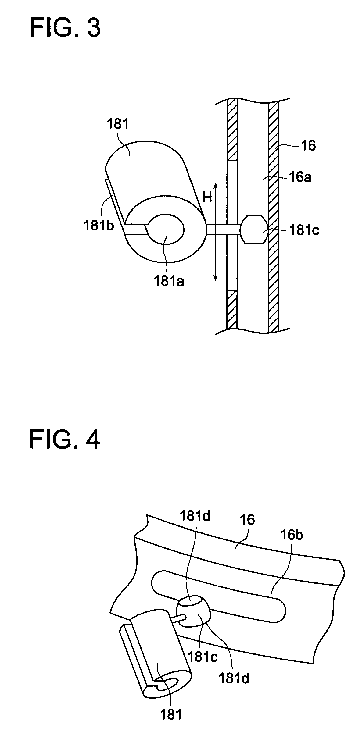
[0032]First, the external view of a HMD 1 in Embodiment 1 will be described, referring to FIG. 1. FIG. 1 is a perspective view of the HMD 1 in accordance with the invention, viewed from the left oblique front.

[0033]The HMD 1 is a head mount type image display apparatus, which is arranged adjacent to an eye of a wearer to be used. The HM 1 is provided, as shown, with a LCD display section 11, eyepiece optical system 12, transparent substrate 13, bridge 14, frame 15, temples 16 and 17, speaker (earphone) 18, speaker support member 181, and the like. The HMD 1 takes in a content image, video or television for example, and sound from an external I / F, not shown, displays the taken-in image on the LCD display section 11, and guides the displayed image to the eye of the wearer via the eyepiece optical system 12. Further, the HMD 1 guides the taken-in sound to the ear of the wearer via the speaker 18.

[0034]The bridge 14 is provided with nose pads 141 and 142 that hold the HMD ...

embodiment 2

[Embodiment 2]

[0068]Now, a HMD 1 in a second embodiment will be described. As the main structure is almost the same as in Embodiment 1, described above, detailed descriptions will be omitted, and temples and a speaker support member having different structures from those in Embodiment 1 will be described, referring to FIG. 6. FIG. 6 is a perspective view of the HMD 1 in accordance with the present embodiment, viewed from the left oblique front.

[0069]The temple in Embodiment 2 is constituted with first temples 216 and 217 and second temples 218 and 219, as shown in FIG. 6.

[0070]The first temples 216, 217 and second temples 218, 219 are long-shaped members constructed of an elastic material having flexibility or the like, and are arranged on the right and left of the frame 15 in pairs. The temples are hung on the temporal regions of head or ears to hold the HMD 1 on the head of the wearer and adjust the wearing position for the wearer. Herein, the first temples 216 and 217 are allowed...


PUM


Abstract

An image display apparatus, which is mounted on a head or face of a wearer attachably and detachably and allows the wearer to view an image and hear sound, includes a long formed temple supported by a temporal region of head or an ear when the wearer is wearing the image display apparatus; a speaker that generates sound, a sound generating face thereof being insertable into the ear at a vicinity of an opening of the ear; and a position adjusting mechanism that holds the speaker, attachably to and detachably from the temple, and movably at least substantially along a surface of the temporal region of the head.

Description

[0001]This application claims priority on Japanese Patent Application No. 2006-146353 filed on May 26, 2006 in the Japanese Patent Office, the entire content of which is hereby incorporated by reference.FIELD OF THE INVENTION[0002]In present invention relates to an image display apparatus, and particularly relates to a head mount type image display apparatus that allows viewing an image and listening sound.BACKGROUND OF THE INVENTION[0003]In recent years, there have been developed head mount type image display apparatuses, namely HMDs (Head Mount Display), for the purposes of appreciation of content images such as movies and video, and remote operation of industrial devices or medical devices, and the like.[0004]A HMD is mounted on the head or face of an observer attachably and detachably, and directly projects an image onto an eye of the observer by an eyepiece optical system, the image obtained from an image display device such as a liquid crystal display device and inorganic EL, ...

Claims


Application Information

Patent Timeline
Patent Type & Authority Patents(United States)
IPC IPC(8): H04N7/00G02C5/20H04N7/18H04R25/00
CPCG02B27/0176H04R1/1066H04R1/1016H04R5/0335
Inventor TANIJIRI, YASUSHIMITSUI, SEIYAMAGUCHI, HIROSHI
Owner KONICA MINOLTA INC
Why Eureka
Try Eureka