Upper troposphere and lower stratosphere wind direction, speed, and turbidity monitoring using digital imaging and motion tracking

a technology of motion tracking and digital imaging, applied in the field of data processing system, can solve problems such as complex and expensive equipmen

Inactive Publication Date: 2012-05-08
IBM CORP
View PDF9 Cites 30 Cited by
  • Summary
  • Abstract
  • Description
  • Claims
  • Application Information

AI Technical Summary

Problems solved by technology

These methods generally require complex and expensive equipment, such as electromagnetic emission and detection apparatus, and are typically only able to capture information from a small geographical area.

Method used


Image

  • Upper troposphere and lower stratosphere wind direction, speed, and turbidity monitoring using digital imaging and motion tracking
  • Upper troposphere and lower stratosphere wind direction, speed, and turbidity monitoring using digital imaging and motion tracking
  • Upper troposphere and lower stratosphere wind direction, speed, and turbidity monitoring using digital imaging and motion tracking

Examples


Embodiment Construction

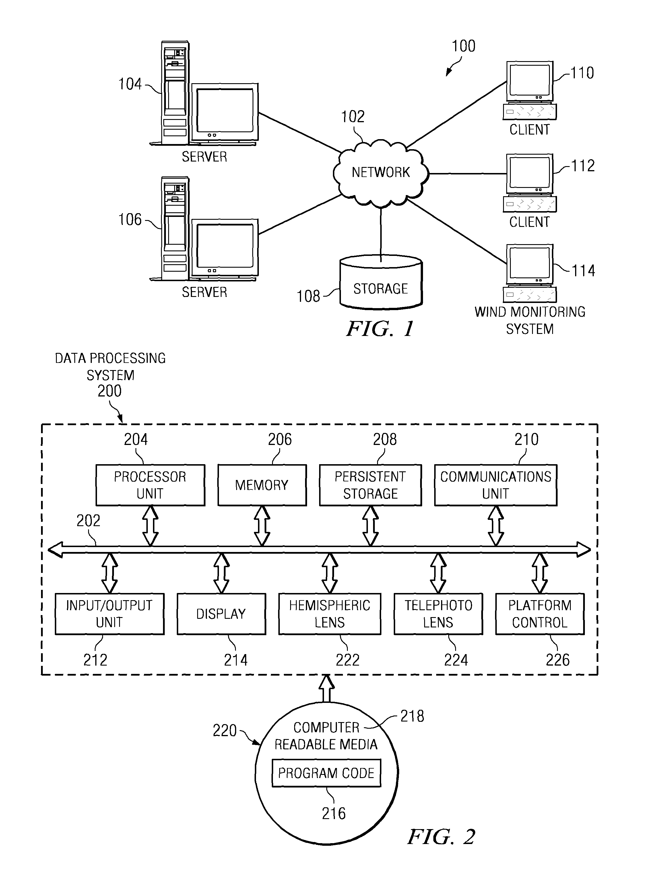
[0014]As will be appreciated by one skilled in the art, the present invention may be embodied as a system, method, or computer program product. Accordingly, the present invention may take the form of an entirely hardware embodiment, an entirely software embodiment (including firmware, resident software, micro-code, etc.) or an embodiment combining software and hardware aspects that may all generally be referred to herein as a “circuit,”“module,” or “system.” Furthermore, the present invention may take the form of a computer program product embodied in any tangible medium of expression having computer usable program code embodied in the medium.

[0015]Any combination of one or more computer-usable or computer-readable medium(s) may be utilized. The computer-usable or computer-readable medium may be, for example, but not limited to, an electronic, magnetic, optical, electromagnetic, infrared, or semiconductor system, apparatus, device, or propagation medium. More specific examples (a no...


PUM


Abstract

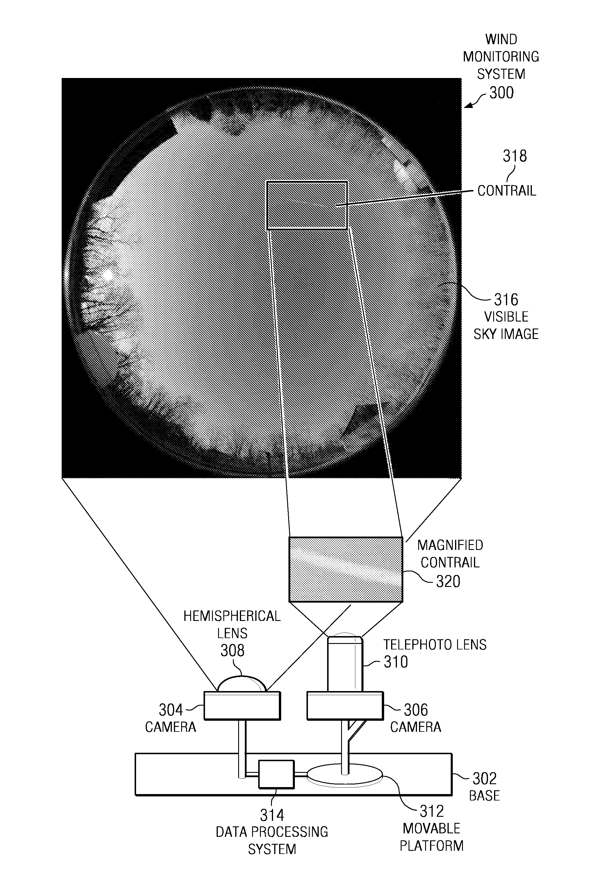
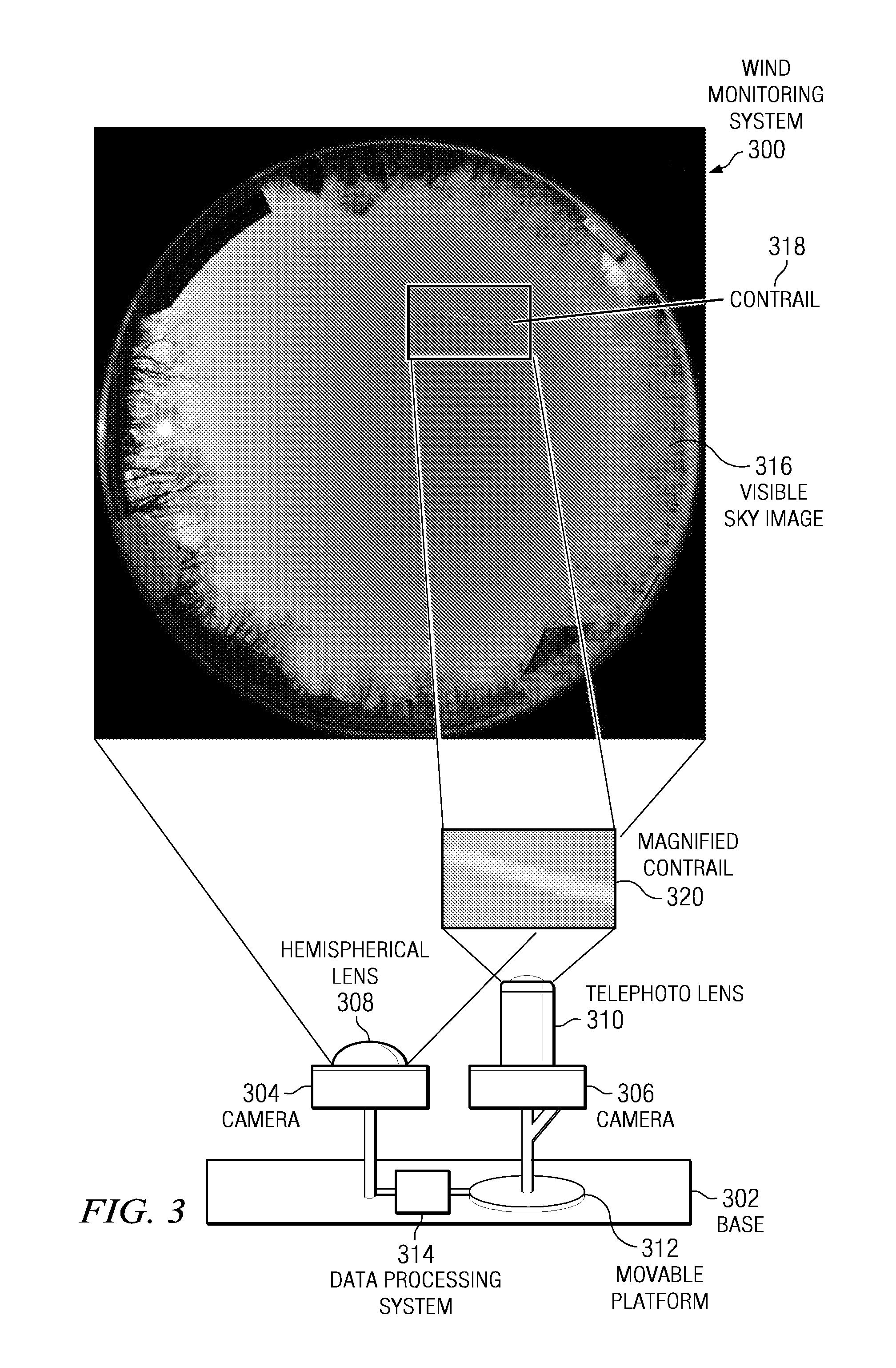
A computer implemented method, apparatus, and computer program product for monitoring wind direction, speed, and turbidity. The visible sky is monitored by a set of cameras for contrails produced by a high-altitude aircraft. In response to identifying a contrail, the contrail is tracked across the field of view of the camera. Contrail data generated when the contrail is identified and during the tracking of the contrail is stored. The contrail data describes characteristics of the contrail including the spread of the contrail and the movement of the contrail across the field of view of the camera. Coordinates of the high-altitude aircraft are determined and compared with the contrail data to identify wind conditions.

Description

BACKGROUND OF THE INVENTION[0001]1. Field of the Invention[0002]The present invention relates generally to an improved data processing system and more specifically to measurements of wind conditions. More particularly, the present invention is directed to a computer implemented method, apparatus, and computer usable program code for monitoring wind direction, speed, and turbidity using digital imaging and / or motion tracking.[0003]2. Description of the Related Art[0004]Several methods exist to determine wind conditions. Existing solutions include wind measurement systems using lasers, winds aloft estimation through radar observation of aircraft, and weather balloons. These methods generally require complex and expensive equipment, such as electromagnetic emission and detection apparatus, and are typically only able to capture information from a small geographical area. Additionally, it is often necessary to mount the equipment to an aircraft in order to obtain accurate wind condition...

Claims


Application Information

Patent Timeline
Patent Type & Authority Patents(United States)
IPC IPC(8): G06K9/00G06K9/40G06V20/00
CPCG01W1/08G06K9/00624G06V20/00
Inventor HARRINGTON, NATHAN JOHN
Owner IBM CORP
Why Eureka
Try Eureka