[0018]In accordance with the present invention a Raman optical probe is produced by preparing an assembly which comprises a central tube surrounded by the collection fibers, which assembly is formed by use of epoxy or the like and polished. This readily enables the use of any size fiber, since problems with fiber alignment, which for years have plagued most methods of probe manufacture, are not an issue with this design. Even in the case where the fibers are of a very small diameter, the ultimate epoxied assembly is larger and therefore easier to work with. The center excitation fiber, positioned within a needle tube (typically a nitinol tubing that may be center less ground) can be inserted inside this main tube. A band pass filter is thinned to a thickness which allows the use of a small diameter excitation fiber. As the laser beam expands after it exits the fiber end face it travels through the filter substrate, preferably a fused silica, and if the thickness of the filter is chosen properly the beam will be the same diameter as the band pass filter has been machined to. The nitinol tube provides an excellent laser shield, so crosstalk of reflected laser light off the surface of the band pass filter substrate is stopped before it can make it to the collection fibers or long pass filter. In addition, having some type of needle tube, illustrated by, but not limited to a nitinol needle tube around the excitation fiber insures that if the band pass filter has any chipping or cracks on the outside edges of the filter from the machining process, these flaws will be over the needle tube and not over the fiber. These imperfections would affect the filter performance if they were above the excitation fiber and the probe would not perform as well as it could. Alternatively, this problem could be addressed by use of a fiber with a wide cladding, so the chipping would be over the cladding.
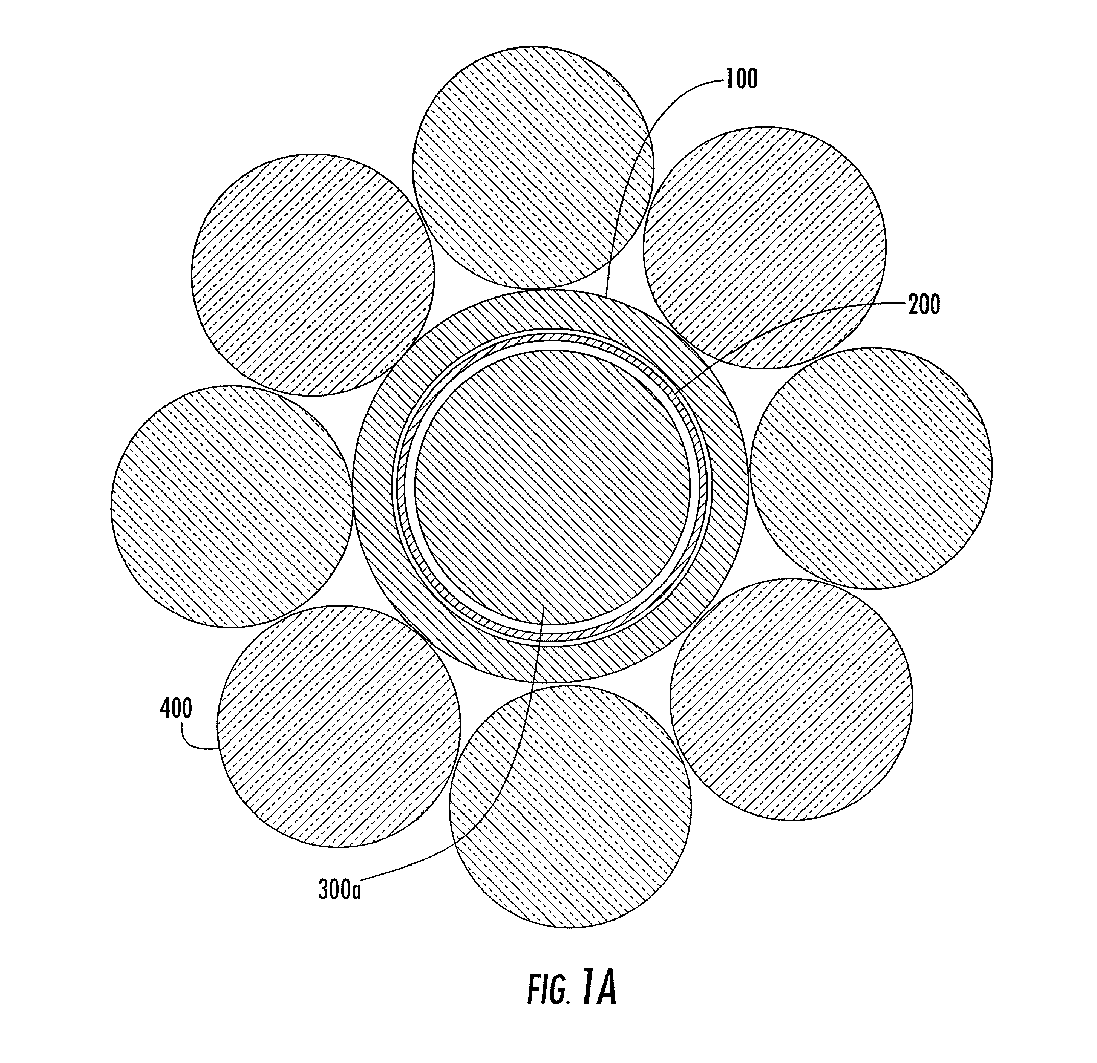
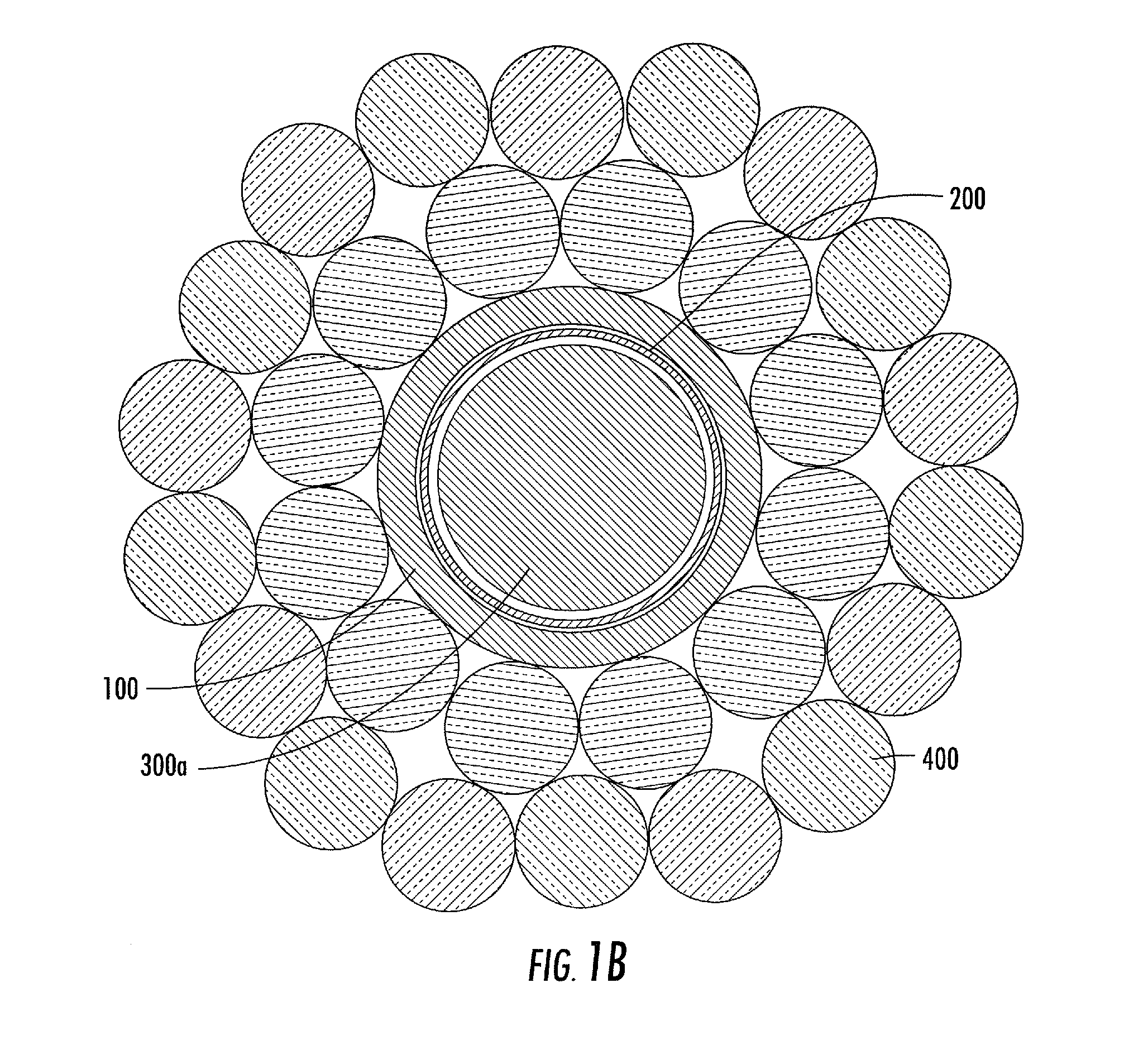
[0020]Normally, one would want the collection fibers to be as close to the excitation fiber as possible. Any gap between the fibers will normally reduce the performance of the probe. This is true for probes in which the fibers end faces stop at the same position (a standard old designed probe), but in the instantly disclosed design, the collection fibers are recessed back from the end face of the excitation assembly. This allows the collection beam of the collection fiber to expand through the donut filter, and this collection cone can collect Raman scattered light directly from the side of the excitation assembly. This construction enables an individual collection fiber to collect a similar amount of Raman light as compared to more conventional designs, even though it is not in intimate contact with the excitation assembly. This configuration also enables the use of a greater number of collection fibers surrounding the excitation. The thickness of the donut filter can be chosen and machined to whatever thickness is best for the particular diameter of the main tube, and thereby maximize the performance of the probe.
[0021]This design also facilitates the use of very small collection fibers. This is very important since the fibers entering the spectrograph must be stacked one on top of each other into a line, and the width of this line affects the resolution of the spectrograph. Normally a fixed slit of 50 or 100 microns is placed at the entrance of the spectrograph to control this. If the fibers are large in relation to this slit, say a 300 micron core, the majority of the light collected is wasted or thrown away since it never really enters the spectrograph. The instantly disclosed design allows easy use of these small fibers since they are epoxied together around the main tube and handled as one assembly which the filter is placed upon. Utilizing small fibers also has advantages in flexibility, and smaller bend radii which enables usefulness in more applications such as endoscopic and catheter based measurements. Prior art designs required the technician to handle each fiber alone which is tremendously difficult and time consuming, and the ability to keep each fiber clean prior to assembly is problematic. Since every design will utilize a greater number of small diameter fibers than large diameter fibers, this has historically been a large problem in prior art designs.
[0022]Accordingly, it is a primary objective of the instant invention to provide fiber optic probes which incorporate a series of graduated shaped and nestable members, e.g. cylindrical annular members which enable uniform and repetitive construction and assembly of the probes resulting in a high degree of quality control.
[0023]It is a further objective of the invention to provide an alternative construction wherein the collection fibers follow a shaped machined tip which enables the user to collect a signal from very close to the excitation laser or delivery element.
[0025]It is a still further objective to provide a process for fiber optic assembly which provides a series of graduated shaped and nestable members, e.g. cylindrical annular members to insure uniform and repetitive alignment and fiber positioning, thereby substantially eliminating misalignment and resulting in a high degree of quality control.

