
Shield for helmet, and helmet including such shield

a shield and helmet technology, applied in the field of shields for helmets, can solve the problems of shields that cannot be worked very well, shield strength may be impaired, etc., and achieve the effect of effective correcting shield drawbacks and simple arrangemen

Inactive Publication Date: 2012-05-15
SHOEI CO LTD
View PDF20 Cites 11 Cited by
  • Summary
  • Abstract
  • Description
  • Claims
  • Application Information

AI Technical Summary

Benefits of technology

The present invention provides a shield for a helmet that can effectively ventilate the helmet while preventing fogging and allowing for better compatibility with different helmet designs. The shield has a simple arrangement with a large number of vent holes formed in a shield main body portion, which allows for well-ventilated interiors of the helmet and prevents wind from entering through the shield. The shield can be attached to a negative pressure generating plate portion or used alone, and it can accelerate the flow of air to flow upward from the vent holes. The invention also provides a helmet with the shield and a pivotal mounting system for the shield.

Problems solved by technology

As the air intake holes must be formed in the original shield itself to extend through it, the shield cannot be worked very well, and the strength of the shield may be impaired.

Method used


Image

  • Shield for helmet, and helmet including such shield
  • Shield for helmet, and helmet including such shield
  • Shield for helmet, and helmet including such shield

Examples


Embodiment Construction

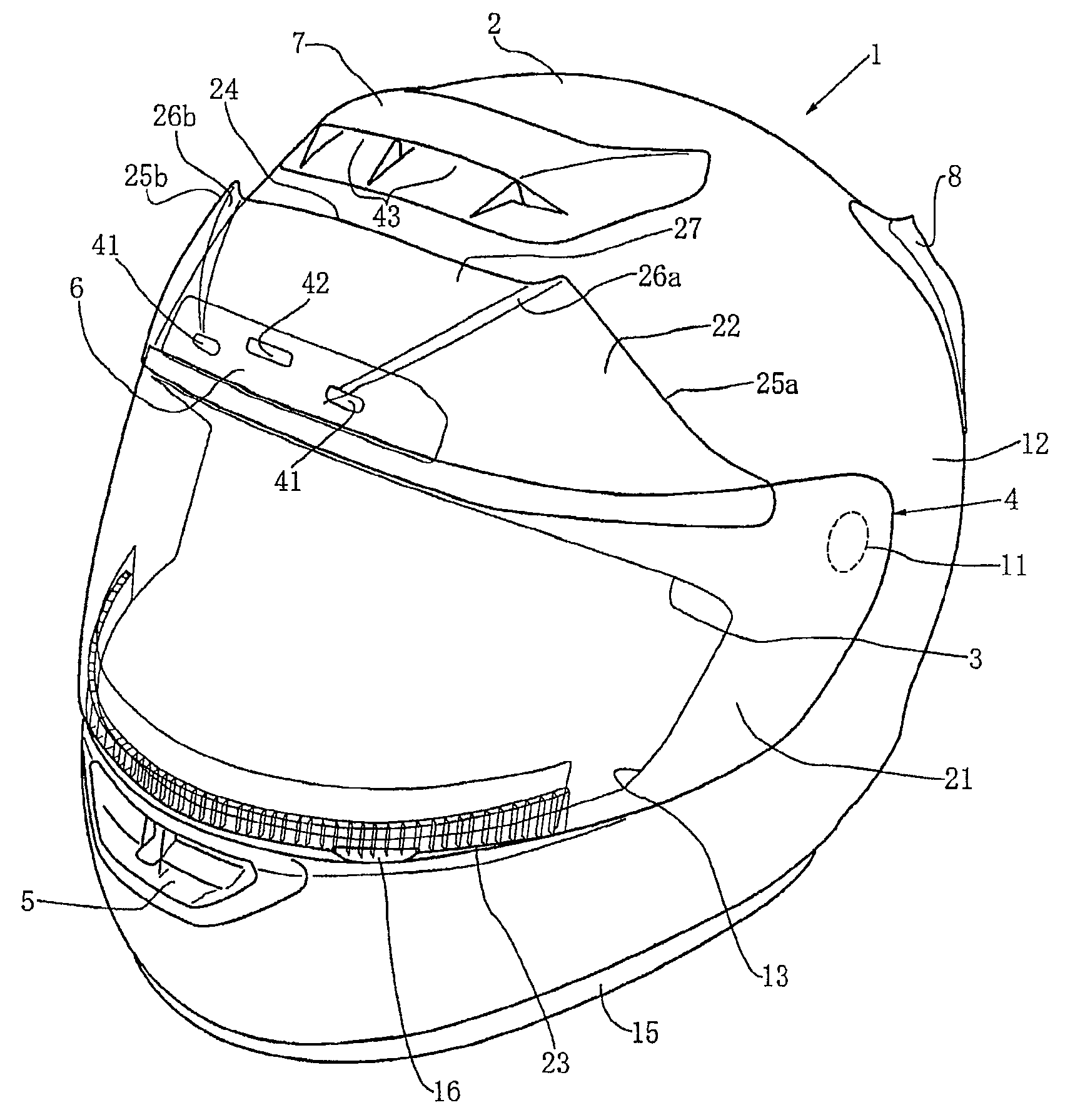
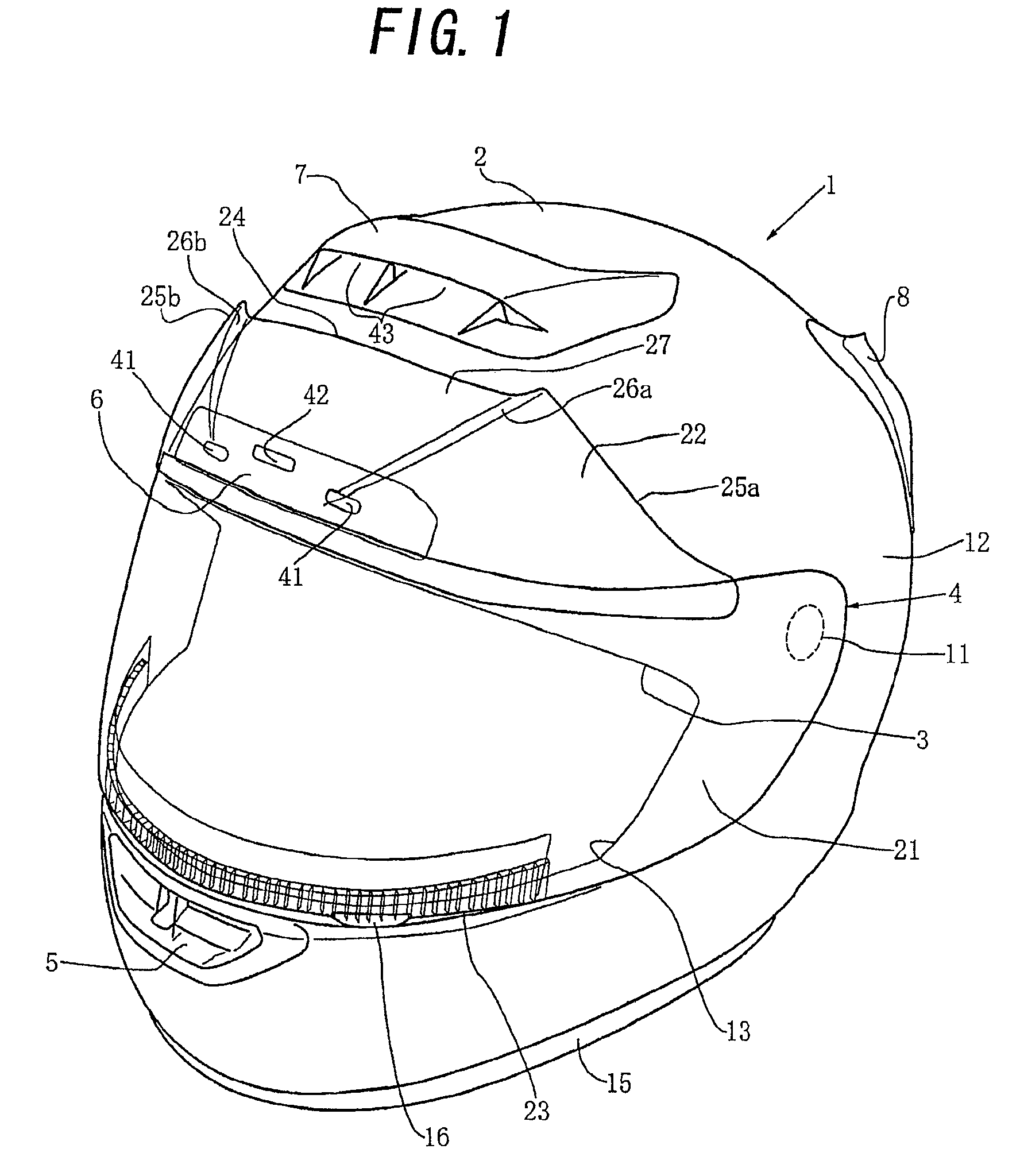
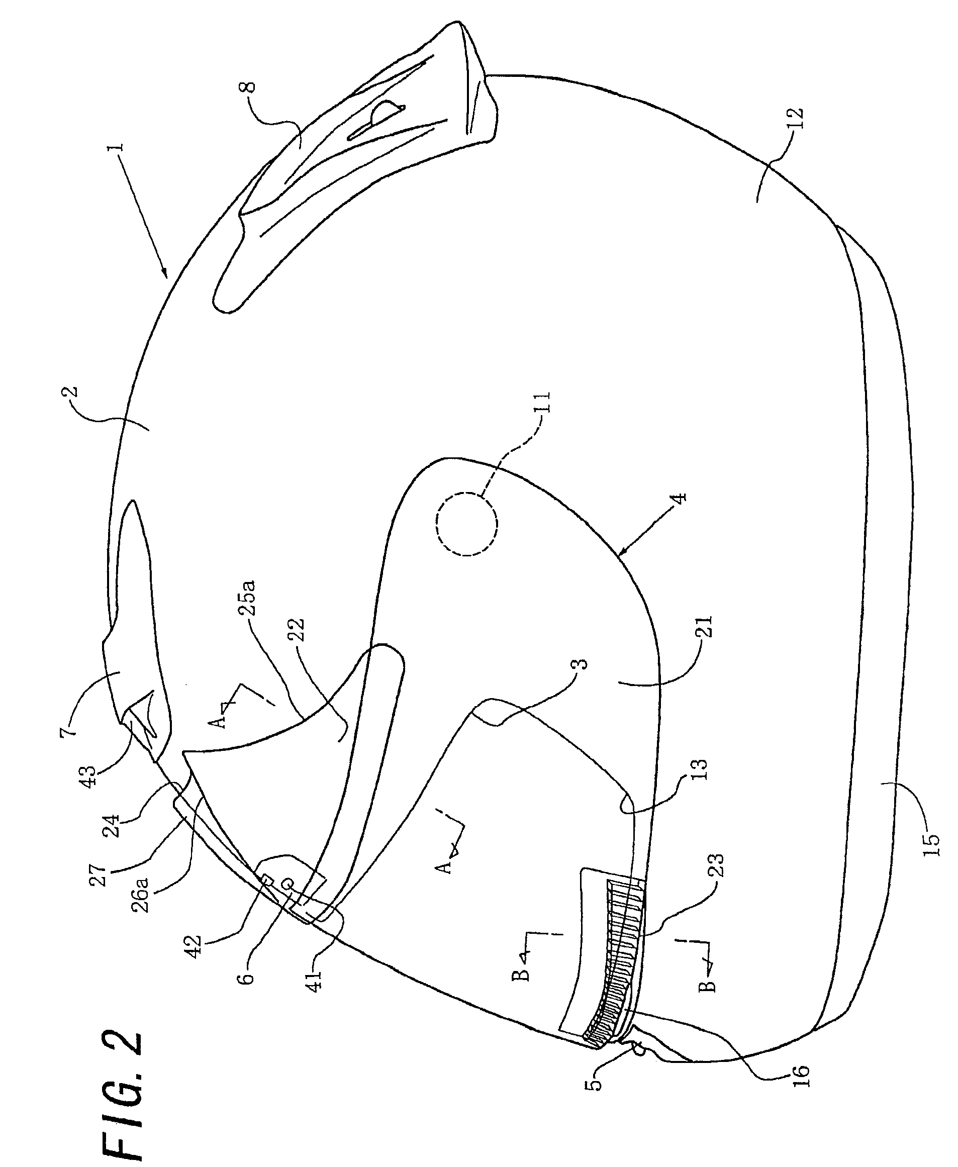
[0027]An embodiment in which the present invention is applied to a full-face-type helmet will be described in “1. Schematic Arrangement of Helmet as a Whole”, “2. Arrangement of Shield” and “3. Operation of Shield” with reference to the accompanying drawings.

[0028]1. Schematic Arrangement of Helmet as a Whole

[0029]As shown in FIGS. 1 and 2, a full-face-type helmet 1 includes:[0030](a) a full-face-type head protecting body 2 to be worn on the head of a helmet wearer such as a motorbike rider,[0031](b) a shield 4 capable of opening / closing a window opening 3 formed in the front surface of the head protecting body 2 to oppose a portion between the forehead and chin (i.e., the central portion of the face) of the helmet wearer, and[0032](c) a pair of left and right chin straps (not shown) attached to the inside of the head protecting body 2.

[0033]As shown in FIGS. 1 and 2, of the head protecting body 2, portions respectively corresponding to the chin, forehead, vertex, back part and / or t...


PUM


Abstract

In a shield for a helmet according to this invention, an air introducing mechanism portion disposed at a region including a lower end portion of a shield main body portion and its vicinity includes a large number of vent holes extending substantially in a vertical direction so that a traveling wind can flow substantially upward from substantially below substantially along the inner surface of the shield main body portion. This invention can provide a shield for a helmet which, despite that raindrops and the like will enter inside the shield main body portion at a low possibility, can introduce the traveling wind inside the shield main body portion well, and in which the shield main body portion can be worked comparatively well and the strength of the shield main body portion is not particularly impaired.

Description

TECHNICAL FIELD[0001]The present invention relates to a shield for a helmet, comprising a shield main body portion and an air introducing mechanism portion disposed at a region including a lower end portion of the shield main body portion and a vicinity thereof. The present invention also relates to a helmet including such a shield.BACKGROUND OF THE INVENTION[0002]In a full-face-type helmet or the like, as disclosed in, e.g., the microfilm of Japanese Utility Model Application No. 51-6012 (Japanese Utility Model Laid-Open No. 52-99024) (to be referred to as “the above patent reference” hereinafter), an air intake hole is formed in a shield so the shield will not fog. In the shield of the helmet disclosed in the above patent reference (to be referred to as “the shield of the above patent reference”), a plurality of comparatively large air intake holes extending through the shield in the direction of thickness are arranged in a region including the lower end portion of the shield and ...

Claims


Application Information

Patent Timeline
Patent Type & Authority Patents(United States)
IPC IPC(8): A42B1/08
CPCA42B3/24A42B3/281
Inventor TSUZUKI, MOICHI
Owner SHOEI CO LTD
Learn More