System and method for obstruction deflection

Active Publication Date: 2012-05-15
UNITED STATES OF AMERICA THE AS REPRESENTED BY THE SEC OF THE ARMY
View PDF17 Cites 6 Cited by
  • Summary
  • Abstract
  • Description
  • Claims
  • Application Information

AI Technical Summary

Benefits of technology

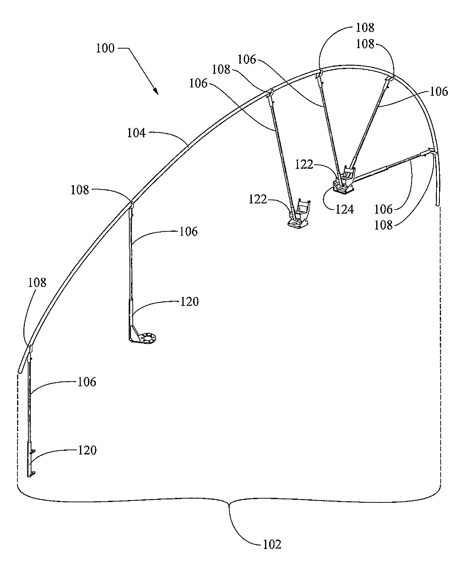
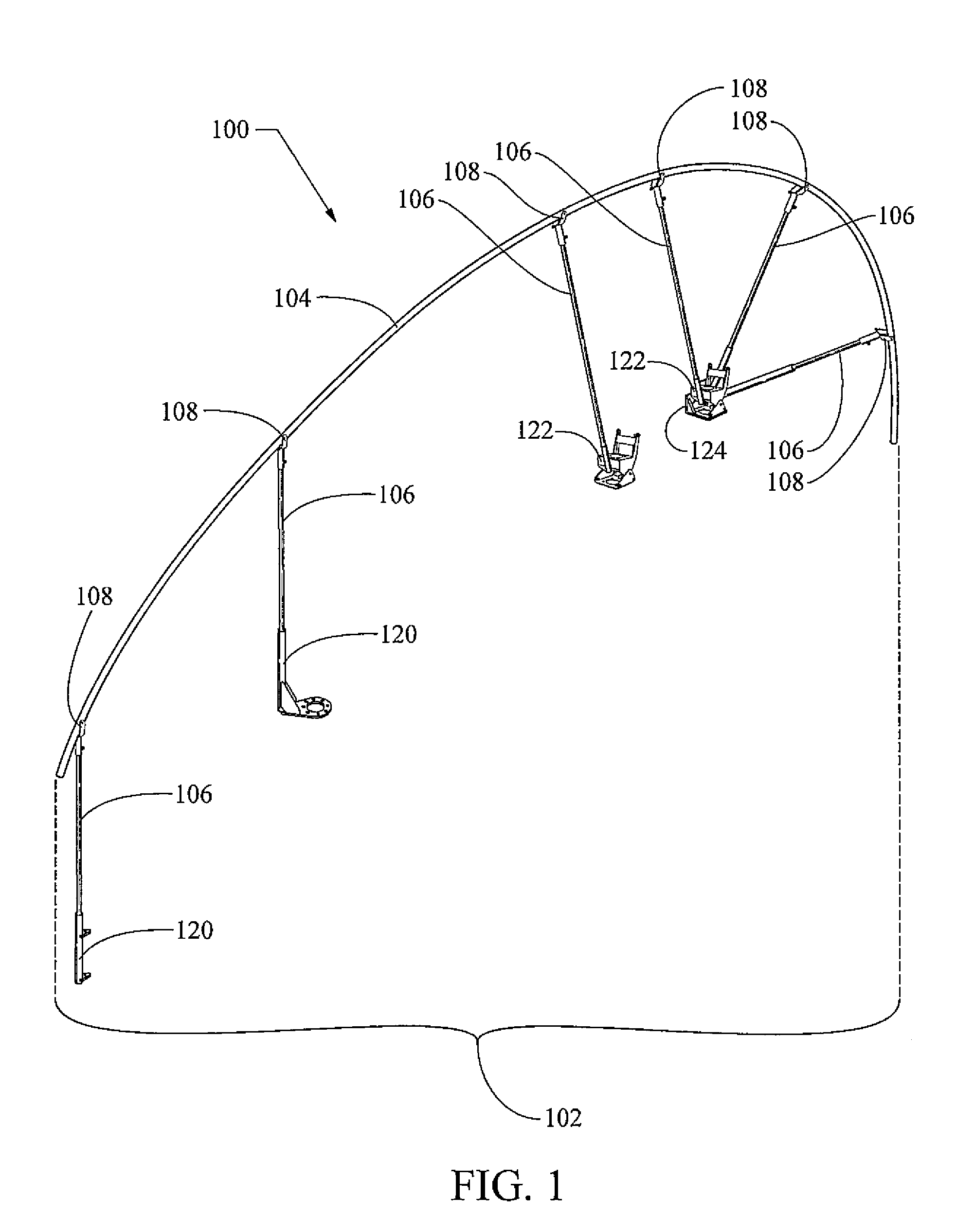
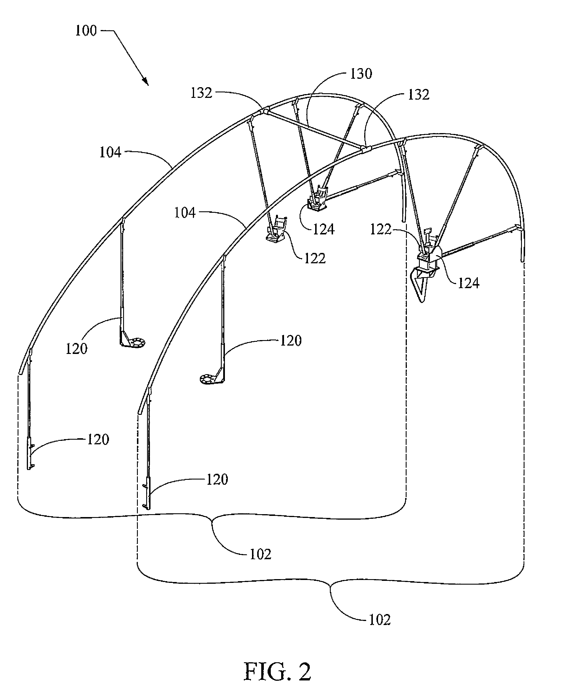
[0011]Attachments are generally mounted on the outer surface of the vehicle, and the guide extends from the vehicle at a distance beyond the distance at which the attachments extend from the vehicle such that the system provides obstruction deflection protection to the vehicle and to the attachments.
[0021]Attachments are generally mounted on the outer surface of the vehicle, and the guide extends from the vehicle at a distance beyond the distance at which the attachments extend from the vehicle to provide obstruction deflection protection to the vehicle and to the attachments.

Problems solved by technology

Moving vehicles can encounter obstructions that interfere with the vehicle or with attachments that are affixed to the outside of the vehicle.
Overhead obstructions can be particularly problematic as conventional metal bar obstruction deflection systems can snag on the obstructions thus causing damage to the obstruction deflection systems and, similarly, conventional metal bar obstruction deflection systems can snag on the obstructions causing damage to the obstruction (e.g., disrupting utility service, defacing infrastructures, scarring trees, destroying foliage, etc.).
Some conventional systems include a tilt or “break away” feature (e.g., spring loaded tilt and reset mechanism); however, many of such conventional systems only operate when the vehicle is moving in one direction (e.g., forward).
When operated in another direction (e.g., vehicle reverse direction), such conventional systems are often ineffective.
Even systems that operate in both forward and reverse vehicle directions often snag on the obstruction rather than deflect the obstruction.
Further, such conventional systems may be complex, expensive, and prone to failure.
Yet further, metal bar conventional deflection systems can present interference or reduction in performance to the electromagnetic operation of antennas that are protected from physical damage by the deflection system; and occupants of the vehicles can suffer electrocution when electric utility lines are encountered by metal bar conventional deflection systems.

Method used


Image

  • System and method for obstruction deflection
  • System and method for obstruction deflection
  • System and method for obstruction deflection

Examples


Embodiment Construction

)

Definitions and Terminology

[0042]The following definitions and terminology are applied as understood by one skilled in the appropriate art.

[0043]The singular forms such as “a,”“an,” and “the” include plural references unless the context clearly indicates otherwise. For example, reference to “a material” includes reference to one or more of such materials, and “an element” includes reference to one or more of such elements.

[0044]As used herein, “substantial” and “about”, when used in reference to a quantity or amount of a material, characteristic, parameter, dimension, and the like, refer to an amount that is sufficient to provide an effect that the material or characteristic was intended to provide as understood by one skilled in the art. The amount of variation generally depends on the specific implementation. Similarly, “substantially free of” or the like refers to the lack of an identified composition, characteristic, or property. Particularly, assemblies that are identified as ...


PUM


Abstract

A system and a method for obstruction deflection for a vehicle. The system generally includes a guide; and a support structure. The support structure includes one or more supports; one or more guide connectors; a fixed single support bracket; a tilt bracket; and a fixed multiple support bracket. The fixed single support bracket, the tilt bracket, and the fixed multiple support bracket are mounted to the vehicle, a first end of each of the supports is installed onto the fixed single support bracket, the tilt bracket, and the fixed multiple support bracket, a second end of each of the supports is installed onto the guide connectors, and the guide is rotatably attached to the guide connectors such that the guide is positioned longitudinally on the vehicle and the guide is curved with the vehicle on the inside of the curve. When the tilt bracket is locked to prevent tilting, and the vehicle is operated in either of a first direction and a second direction, and an obstruction is encountered by the guide, cooperative flexing of the guide and of the supports in combination deflects the obstruction away from the vehicle.

Description

GOVERNMENT INTEREST[0001]The invention described here may be made, used and licensed by and for the U.S. Government for governmental purposes without paying royalty to us.BACKGROUND OF THE INVENTION[0002]1. Field of the Invention[0003]The present invention generally relates to a system and a method for obstruction deflection.[0004]2. Background Art[0005]Moving vehicles can encounter obstructions that interfere with the vehicle or with attachments that are affixed to the outside of the vehicle. Such obstructions include naturally occurring objects such as tree limbs, branches, vines, brush, and the like; and man-made objects such as wires, fences, cables, signs, bridges, and the like. Conventional systems for deflection of such obstructions are typically rigid metal bars. Overhead obstructions can be particularly problematic as conventional metal bar obstruction deflection systems can snag on the obstructions thus causing damage to the obstruction deflection systems and, similarly, c...

Claims


Application Information

Patent Timeline
IPC IPC(8): F41H5/02
CPCB60R19/54F41H11/11
Inventor ROSE, MICHAEL T.MANIACI, JOHN J.
Owner UNITED STATES OF AMERICA THE AS REPRESENTED BY THE SEC OF THE ARMY
Why Eureka
Try Eureka