Aircraft target display

a technology for aircraft and target displays, applied in weapons, analogue computers, hybrid computing, etc., can solve the problems of increasing pilot workload, unnecessarily restricting aircraft's freedom to alter flight paths, and needing to comply with pre-planned flight conditions and approach paths, so as to facilitate an attack and ease the workload of pilots.

Active Publication Date: 2012-05-15
BAE SYSTEMS PLC
View PDF11 Cites 0 Cited by
  • Summary
  • Abstract
  • Description
  • Claims
  • Application Information

AI Technical Summary

Benefits of technology

[0006]Such an arrangement provides real-time feedback to the pilot of the “degree of freedom” that exists with regard to the range to the target(s) of interest. The display, which is preferably a head up display (HUD), gives a clear indication to the pilot as to when, on the current flight path and at current flying conditions (e.g. speed), a weapon or weapons can be released and it / they will be capable of engaging the target(s) of interest. The position of the aircraft position indicator relative to the weapon launch acceptable region is a simple and easily assimilated display: if the aircraft position indicator lies within the bounds of the earliest and latest weapon release points then the pilot can see that the weapon, if released immediately, is capable of engaging the target. If the aircraft position indicator is outside the weapon launch acceptable region, either the aircraft is still approaching the target and the pilot must wait for the target to come into range before engaging the target, or the aircraft is heading away from the target and the weapon is incapable of engaging the target unless the aircraft changes its flight path back towards the target. Continuously generating a weapon launch acceptable region enables the extraction and manipulation of information so as to provide a real-time display which can be readily assimilated by the pilot in order to ease decision-making.
[0010]This maximum lateral offset allowance is intermixed with the weapon launch acceptable region as these are displayed in the pilot's field of view, preferably along perpendicular axes. The symbols may be displayed so as to represent the weapon launch acceptable region along the vertical axis, and the maximum lateral offset along the horizontal axis. The former is intuitively recognised by the pilot as being a plan view, with the aircraft's instantaneous direction of travel (being in the same vertical axis as the weapon launch acceptable region.) The latter is equally intuitive to the pilot, being recognised as representing the degree of freedom in relation to the maximum allowable heading away from the or each target from the pilot's visual perspective. A practical form of display is in the form of a rectangular box in the field of view of the pilot; the top and bottom horizontal edges of the box define the weapon launch acceptable region and the vertical edges define the instantaneous maximum lateral offset. The box may be aligned along a vertical axis centred in the pilot's field of view (and / or aligned with the front of the aircraft). The aircraft's instantaneous position and direction of travel relative to the box is indicated by a single symbol. To facilitate an attack, the symbol may be aligned such that it resides within this box. As the aircraft's position, direction of flight and flight conditions (e.g. altitude, airspeed) change, so does the location, size and shape of the box displayed, but provided the pilot can see that the aircraft position / direction of travel symbol lies within the box it will be readily apparent that at that moment the weapon is capable of engaging the target. Conversely, if the symbol is outside the box the pilot can readily see that the weapon is not presently capable of engaging the target, because the aircraft is too far away from / close to the target and / or the aircraft is bearing away from the target at too great an angle; thus the pilot can easily decide the appropriate action in order to engage the target: wait until the target is within range, change course, etc.
[0011]Weapon launch acceptable regions and maximum lateral offsets may be calculated for each of several targets simultaneously, with this information being amalgamated such that display symbols for each of these may be displayed simultaneously, in the manner established for a single target, in the pilot's field of view. The multiple weapon launch acceptable regions and maximum lateral offsets are amalgamated so as to generate a compound display symbol representing the regions and offsets common to at least two and preferably all of the targets, and symbols are generated representing the instantaneous aircraft position and bearing, and all of these symbols are displayed simultaneously. This provides the pilot with a display including a single compound box representing two or more targets having common instantaneous weapon launch acceptable regions and maximum lateral offsets and a single aircraft symbol. Whilst the aircraft symbol resides within the compound box the pilot can readily discern that all those targets contributing to the compound box are engageable, whereas targets whose weapon launch acceptable regions and for maximum lateral offsets do not overlap the compound box are not engageable. Likewise, if the aircraft symbol is outside the compound box, but is still within the weapon launch acceptable region and maximum lateral offset of a single target, the pilot can easily see that that target is currently engageable, but other targets are not engageable. This is discerned by reference to other specific symbols (discussed later). One of the targets displayed may be designated and displayed as the main target of interest, and the associated weapon launch acceptable region and maximum lateral offset symbols aligned within the pilot's field of view. In this way the workload on the pilot is eased, because it is readily discernible from the display and associated reference symbols whether or not the main target of interest is engageable or not, the associated symbology being displayed within the centre of the pilot's field of view. The other targets may not be as important, at that time, as the main target and therefore it is less significant that the symbology identifying these is not centred in the pilot's field of view.

Problems solved by technology

This is unnecessarily restrictive on the aircraft's freedom to alter its flight path in the light of changed circumstances.
However, with the increases in computer power possible as processor technology has advanced, the need to comply with pre-planned flight conditions and approach paths has diminished; computers can now determine dynamic current flight conditions and utilize this information to continuously update the weapon release position.
Aircraft carry more and a greater variety of different weapons, and the battlefield is becoming increasingly dynamic and volatile in nature and this increases the workload on the pilot, who needs to be able to assimilate all the various elements of targeting information and to take decisions not only on whether or not to engage a particular target but also as to the effects of the weapon's ability successfully to engage a given target in the light of past and future changes in flight path.

Method used


Image

  • Aircraft target display
  • Aircraft target display
  • Aircraft target display

Examples


Embodiment Construction

[0027]The present invention will now be described by way of example only and with reference to the accompanying drawings.

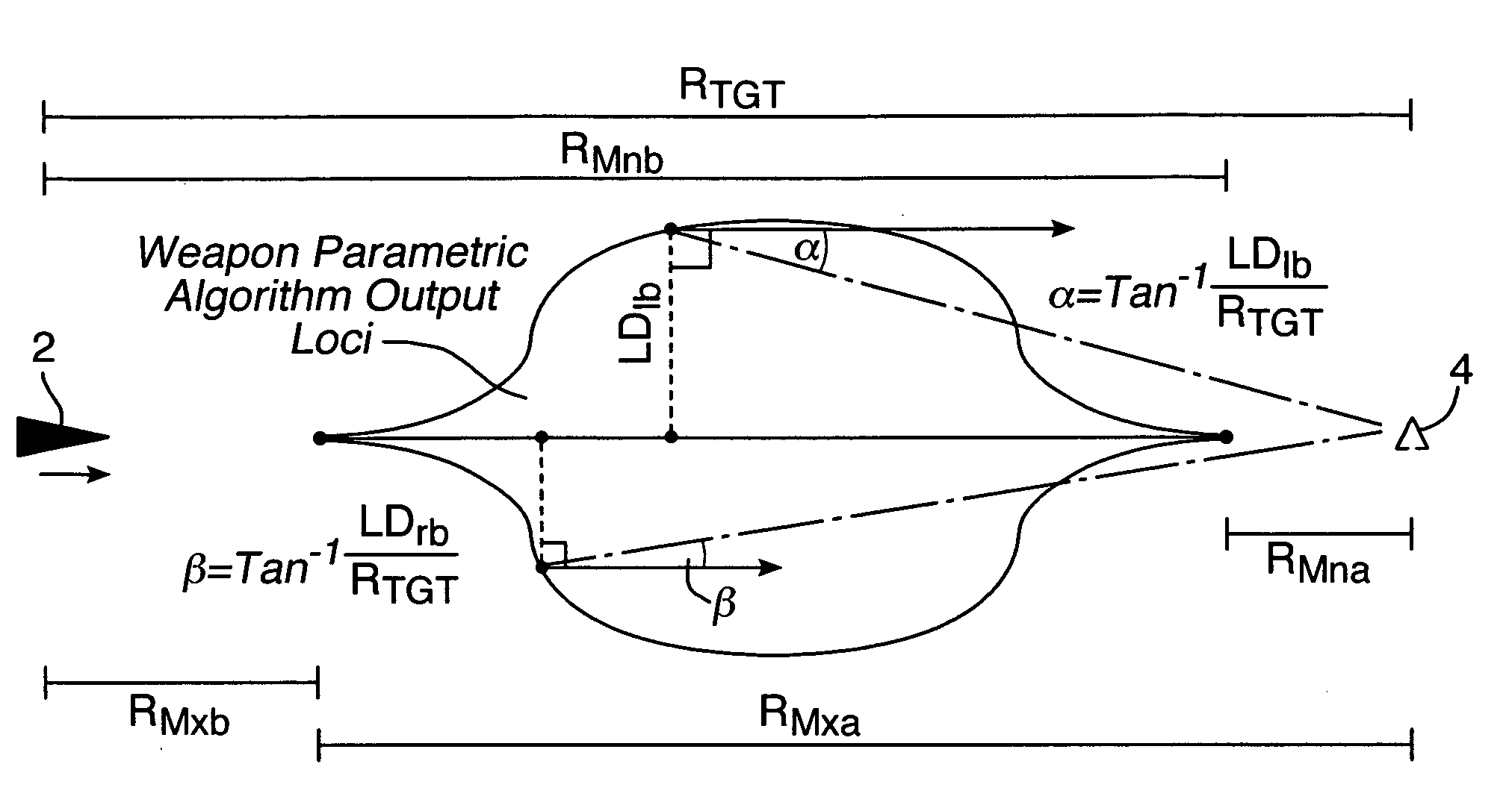
[0028]The present invention involves representing different “degrees of freedom” regarding where the aircraft can afford to be, prior to weapon release, if the weapon is to engage the target. This is inherently dependent on the maneuverability or flight characteristics of the weapon as well as on the position and flight conditions of the aircraft carrying the weapon.

[0029]As an aircraft approaches a target, the earliest possible weapon release point, at which the weapon is capable of engaging the target is dictated by the weapon's ability to prolong its flight path, such as by “pitching up” to induce a glide for as long as possible. The latest possible weapon release point is dictated by the weapon” ability to shorten its flight path. Between the earliest and latest possible weapon release points is a release range envelope, which is the “launch acceptable region”...


PUM


Abstract

A method of displaying target engageability information to a pilot of an aircraft in flight including calculating according to instantaneous aircraft position and motion relative to at least one target to be engaged and to characteristics of a weapon, earliest and latest weapon release points between which the weapon is presently capable of engaging a target of interest and generating display symbols indicating a weapon launch acceptable region and the instantaneous position of the aircraft relative thereto. A system for displaying the information and a target engageability display symbology are also described.

Description

RELATED APPLICATION INFORMATION[0001]This application is a United States National Phase patent application of, and claims the benefit of, International Patent Application No. PCT / GB2006 / 050239 which was filed on Aug. 16, 2006, and which claims priority to British Patent Application No. 0516998.2, which was filed on Aug. 17, 2005, the disclosures of each of which are incorporated herein by reference.FIELD OF THE INVENTION[0002]The present invention relates to the display of targeting information to the pilot of an aircraft in flight, in particular to the display of information relating to the engagement of targets by air-to-surface weapons.BACKGROUND INFORMATION[0003]Conventional air-to-surface weapon delivery relies upon pre-planned flight conditions with a pre-determined weapon release point at an offset from the known and pre-defined target position. This is unnecessarily restrictive on the aircraft's freedom to alter its flight path in the light of changed circumstances. However,...

Claims


Application Information

Patent Timeline
Patent Type & Authority Patents(United States)
IPC IPC(8): G06F19/00
CPCF41G7/007F41G9/002
Inventor HOWARD, MATTHEW JAMES
Owner BAE SYSTEMS PLC
Why Eureka
Try Eureka