
Image forming apparatus and method

a technology of image forming and forming apparatus, which is applied in the direction of electrographic process apparatus, printing, instruments, etc., can solve the problems of not considering the change of image gloss, the inability to achieve images with different gloss levels, and the inability to efficiently and quickly make small prints. achieve the effect of rapid and efficient production of different gloss levels

Inactive Publication Date: 2012-05-15
FUJIFILM CORP
View PDF20 Cites 8 Cited by
  • Summary
  • Abstract
  • Description
  • Claims
  • Application Information

AI Technical Summary

Benefits of technology

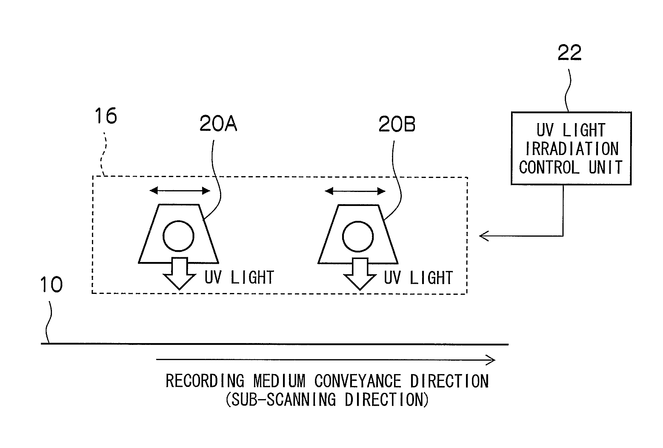
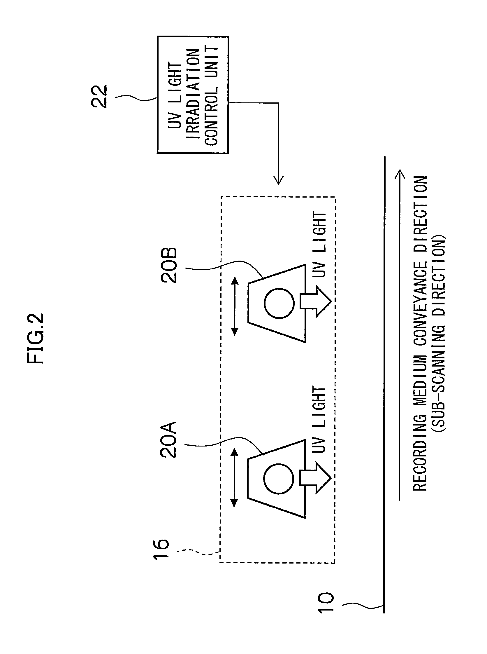
The present invention provides an image forming apparatus and method that can make small numbers of prints with different gloss levels quickly and efficiently. This is achieved by controlling the time period from the deposition of droplets of transparent UV ink until the irradiation of UV light, in accordance with the gloss conditions of the image. The apparatus includes an image forming device, a transparent UV ink droplet ejection device, a UV light irradiation device, a gloss condition setting device, and a UV light irradiation control device. The control device can control the movement of the UV light irradiation device or the intensity of the UV light irradiated. The method includes the steps of forming an image, ejecting and depositing droplets of transparent UV ink, irradiating UV light, setting a gloss condition, and controlling the irradiation timing of the UV light.

Problems solved by technology

Therefore, this method is not suitable for printing small numbers of prints, since there is an increase in the labor input, time and costs, and the like, required in switching the UV-curable varnishes, and hence there is a problem in that small numbers of prints cannot be made efficiently and quickly.
In this method, however, no consideration is given to changing the gloss of the image and it is not possible to achieve images having different gloss levels.

Method used


Image

  • Image forming apparatus and method
  • Image forming apparatus and method
  • Image forming apparatus and method

Examples


Embodiment Construction

[0036]The present invention is able to achieve images having different gloss levels by changing the time until ultraviolet (UV) light is irradiated after the deposition of droplets of transparent UV ink onto the surface of a recording medium (i.e., UV light irradiating timing), and changing the irradiation intensity (exposure amount) of the UV light, in accordance with the gloss conditions (print conditions) of the image.

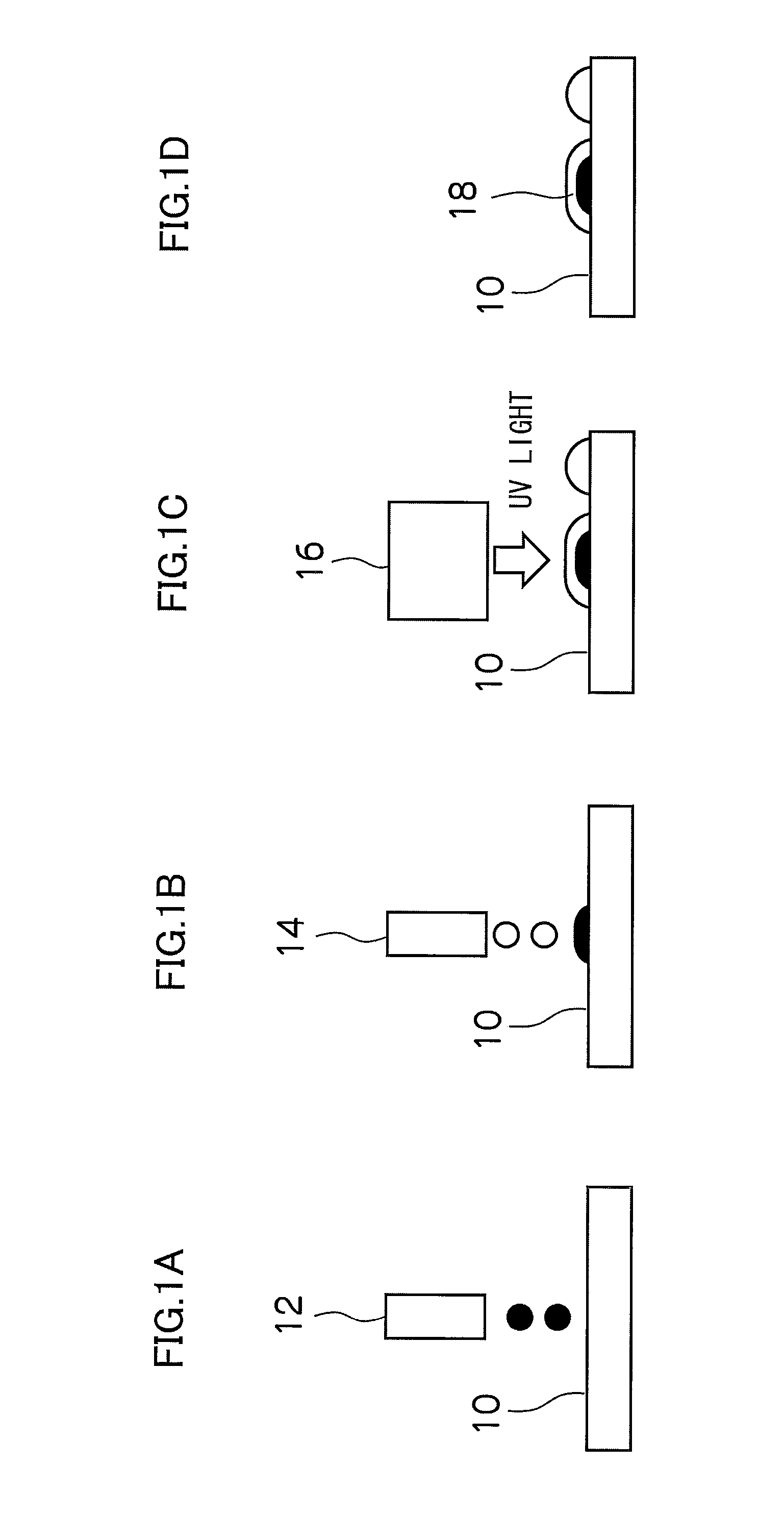
[0037]The overall sequence of the image forming method according to an embodiment of the present invention is described with reference to FIGS. 1A to 1D.

[0038]Firstly, as shown in FIG. 1A, droplets of colored ink are ejected from nozzles (not shown) of an inkjet head (a colored ink head) 12 to form an image on the surface of a recording medium 10. The method for forming the image is not limited to the inkjet method, and it is also possible to employ another method.

[0039]Then, as shown in FIG. 1B, droplets of transparent UV ink are ejected from nozzles of another ink...


PUM


Abstract

The image forming apparatus includes: an image forming device which forms an image on a recording medium; a transparent UV ink droplet ejection device which ejects and deposits droplets of transparent UV ink onto the recording medium; a UV light irradiation device which irradiates UV light onto the transparent UV ink having been deposited on the recording medium; a gloss condition setting device which sets a gloss condition of the image; and a UV light irradiation control device which controls an irradiation timing of the UV light irradiated from the UV light irradiation device in accordance with the gloss condition.

Description

BACKGROUND OF THE INVENTION[0001]1. Field of the Invention[0002]The present invention relates to an image forming apparatus and an image forming method, and more particularly to technology for controlling the level of gloss of an image formed on a recording medium.[0003]2. Description of the Related Art[0004]Japanese Patent Application Publication No. 2006-239685 discloses a method of varnishing an image by an inkjet method, wherein droplets of varnish are deposited in a screen pattern in order to adjust and control the level of gloss. According to this method, an ultraviolet (UV) curable varnish having high fluidity is used if a highly glossy surface is to be formed, while another UV-curable varnish having low fluidity is used if a matte surface of low gloss is to be formed. In other words, it is necessary to switch between the use of different UV-curable varnishes having different wetting properties (fluidities), in order to obtain images having different gloss levels. Therefore, ...

Claims


Application Information

Patent Timeline
Patent Type & Authority Patents(United States)
IPC IPC(8): B41J2/01
CPCB41J2/14233B41J2/155B41J2/2114B41J11/002B41J2002/14459B41J2202/20B41M7/0081B41M7/0045B41J11/00212B41J11/00214
Inventor FUKUI, TAKASHI
Owner FUJIFILM CORP
Learn More