
Instrumentation and method for mounting a surgical navigation reference device to a patient

a reference device and surgical technology, applied in the field of surgical instruments and methods, can solve the problems of increased trauma to the vertebra v/sub>a, inefficient use of surgeon's time, and increased risk of potential infection

Active Publication Date: 2012-05-15
WARSAW ORTHOPEDIC INC
View PDF28 Cites 19 Cited by
  • Summary
  • Abstract
  • Description
  • Claims
  • Application Information

AI Technical Summary

Benefits of technology

The present invention provides improved instrumentation and methods for mounting a surgical navigation reference device to a patient. This allows for more accurate and precise image-guided surgical procedures to be performed on the patient. The instrumentation includes a cannula, a trocar, and a bone anchor, which work together to securely mount the reference device to the patient's bone. The method involves positioning the bone anchor in the bone, inserting the reference device through the cannula, and securing it to the bone anchor. This allows for easy and safe mounting of the reference device, ensuring the accuracy of the surgical procedure.

Problems solved by technology

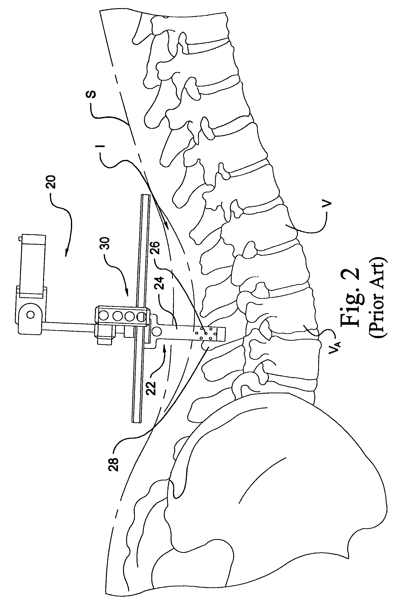
Moreover, the use of fasteners may result in increased trauma to the vertebra VA.
The relatively lengthy wait encountered by the surgeon during this surgical procedure results in inefficient use of the surgeon's time.
Additionally, since acquisition of the radiographic images must be done in an intra-operative setting, there is a higher risk of potential infection because the incision must be open for a relatively lengthy period of time.
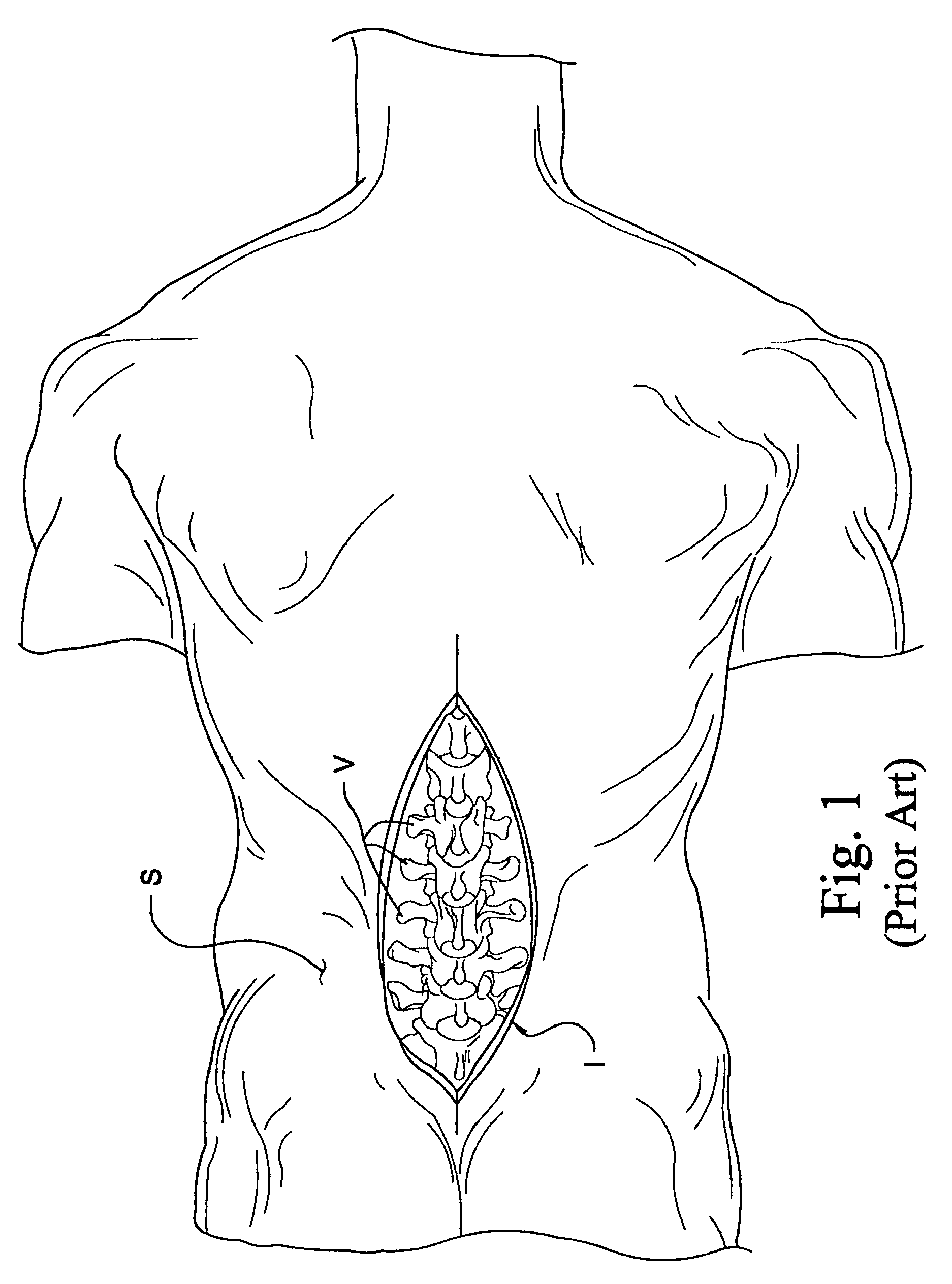
Large surgical incisions are highly invasive and can result in increased trauma, blood loss, post-operative pain, and a lengthy recovery period.

Method used


Image

  • Instrumentation and method for mounting a surgical navigation reference device to a patient
  • Instrumentation and method for mounting a surgical navigation reference device to a patient
  • Instrumentation and method for mounting a surgical navigation reference device to a patient

Examples


Embodiment Construction

[0034]For the purposes of promoting an understanding of the principles of the invention, reference will now be made to the embodiments illustrated in the drawings and specific language will be used to describe the same. It will nevertheless be understood that no limitation on the scope of the invention is hereby intended, and that alterations and further modifications in the illustrated devices and further applications of the principles of the invention as illustrated herein are contemplated as would normally occur to one skilled in the art to which the invention relates.

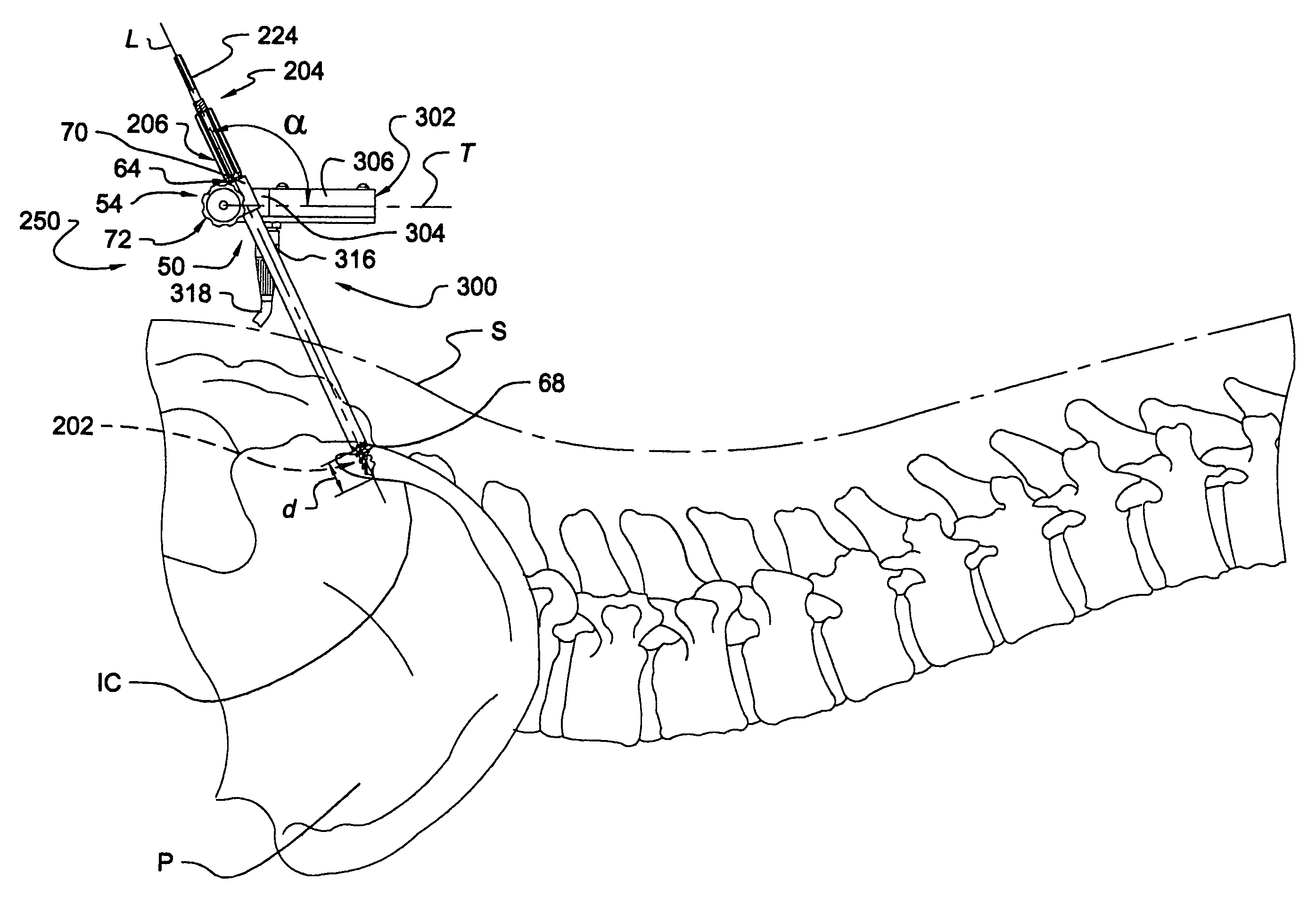
[0035]Referring to FIGS. 3-8, shown therein is surgical instrumentation according to one form of the present invention for use in association with the percutaneous mounting of a surgical navigation reference device to a patient. Although the instrumentation and methods illustrated and described herein are directed to surgical procedures involving the spinal column, it should be understood that applications of the pr...


PUM


Abstract

Instrumentation and methods are provided for mounting a surgical navigation reference frame to a patient. In one embodiment, a trocar is positioned within a cannula to form an insertion device adapted for percutaneous introduction into the patient. A bone anchor having a bone engaging portion is inserted through the cannula for anchoring to bone. The bone anchor cooperates with the cannula to form a mounting device adapted for coupling with the surgical navigation reference frame. In a further embodiment, an image-guided surgical procedure is performed at a location remote from the anchoring location. In a specific embodiment, a minimally invasive surgical procedure is performed adjacent the spinal column, with a reference frame anchored to the pelvic bone, and more specifically to the iliac region of the pelvic bone. In another specific embodiment, a minimally invasive surgical procedure is performed adjacent the hip joint, with a first reference frame anchored to the pelvic bone, and more specifically to the iliac region of the pelvic bone, and with a second reference frame anchored to the femur.

Description

CROSS REFERENCE TO RELATED APPLICATIONS[0001]The present application claims foreign priority benefits and benefit as a continuation of International PCT Patent Application Number PCT / US03 / 11610 filed Apr. 15, 2003, which is a continuation-in-part of U.S. patent application Ser. No. 10 / 124,291 filed Apr. 17, 2002, now U.S. Pat. No. 6,993,374 the contents of each application hereby being incorporated by reference in their entirety.FIELD OF THE INVENTION[0002]The present invention relates generally to the field of surgical instrumentation and methods that utilize image navigation systems to indicate and track the relative position of various anatomical body parts and / or surgical instruments during medical and surgical procedures, and more specifically relates to instrumentation and methods for percutaneously mounting a surgical navigation reference device to a patient.BACKGROUND OF THE INVENTION[0003]Image navigation technology has been developed to indicate and track the relative posi...

Claims


Application Information

Patent Timeline
Patent Type & Authority Patents(United States)
IPC IPC(8): A61B5/05A61B17/34A61B19/00
CPCA61B17/3468A61B2019/5483A61B2019/527A61B2034/207A61B2090/3983
Inventor SASSO, RICARDO
Owner WARSAW ORTHOPEDIC INC
Learn More