
Device for Calorimetric Measurement

Inactive Publication Date: 2011-11-03
THE BOARD OF TRUSTEES OF THE UNIV OF ILLINOIS
View PDF23 Cites 16 Cited by
  • Summary
  • Abstract
  • Description
  • Claims
  • Application Information

AI Technical Summary

Benefits of technology

[0013]To overcome the limitations of previous designs, a single crystal silicon microfabricated calorimeter is provided herein. Silicon has high thermal conductivity, comparable to that of metal, while exhibiting a heat capacity similar to commonly used dielectric materials (silicon dioxide and silicon nitride), thus improving the thermal time constant of the calorimeter. High thermal conductivity also offers better temperature homogeneity within the heater, and thus facilitates improved instrumentation and analysis.

Problems solved by technology

The thermal time constant of the previous designs are often limited by the low thermal conductivity of the dielectric membrane.
Moreover, the metal heater and thermometer generally have long-term stability issues caused by electromigration.
Most previous works on micro differential scanning calorimetry focused on reducing thermal capacity of the device but in general there is a lack of detailed thermal design analysis and experimental validation regarding heating efficiency and response time.

Method used


Image

  • Device for Calorimetric Measurement
  • Device for Calorimetric Measurement
  • Device for Calorimetric Measurement

Examples


example 1

Design, Fabrication and Characterization of a Silicon Microfabricated Calorimeter

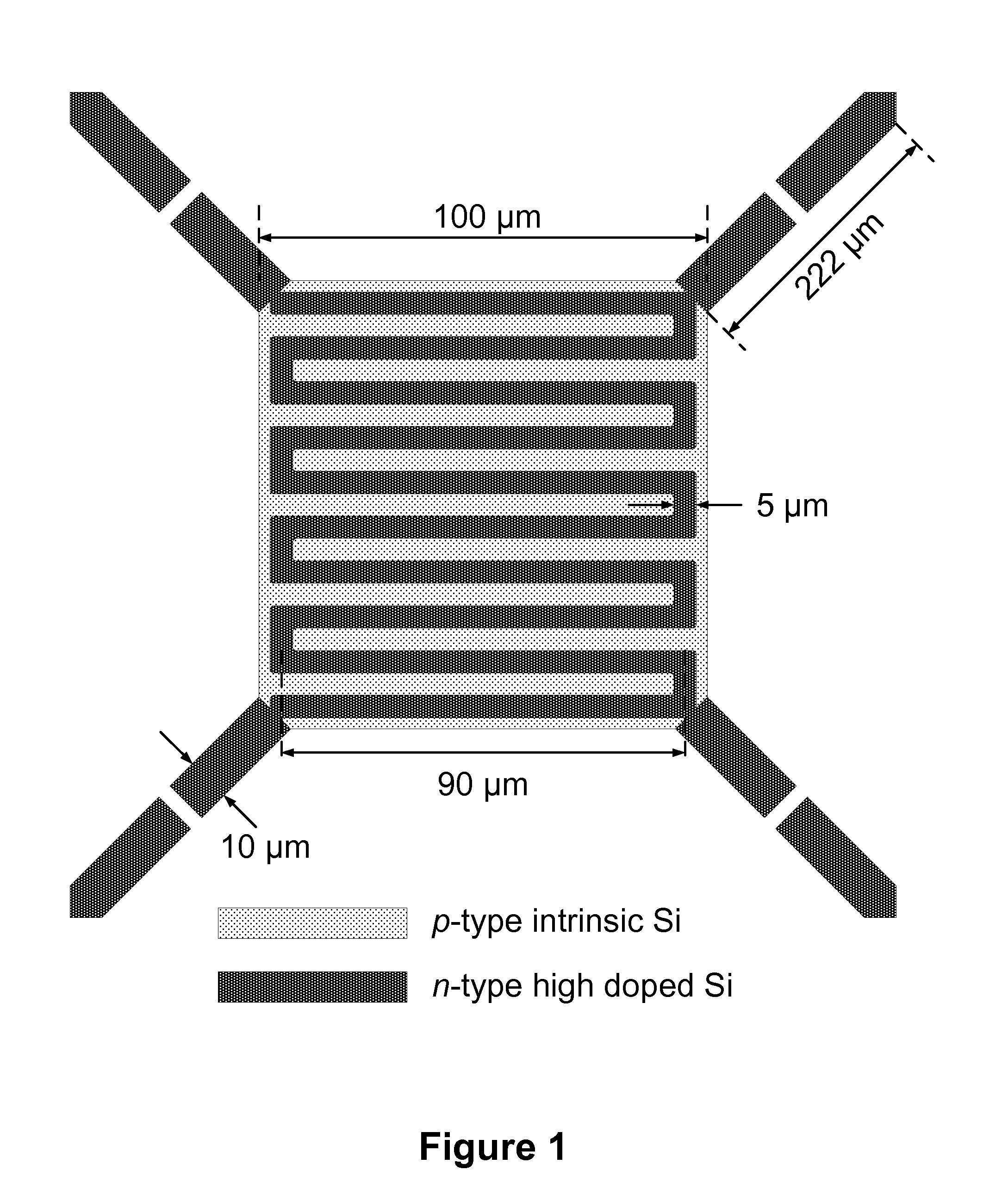
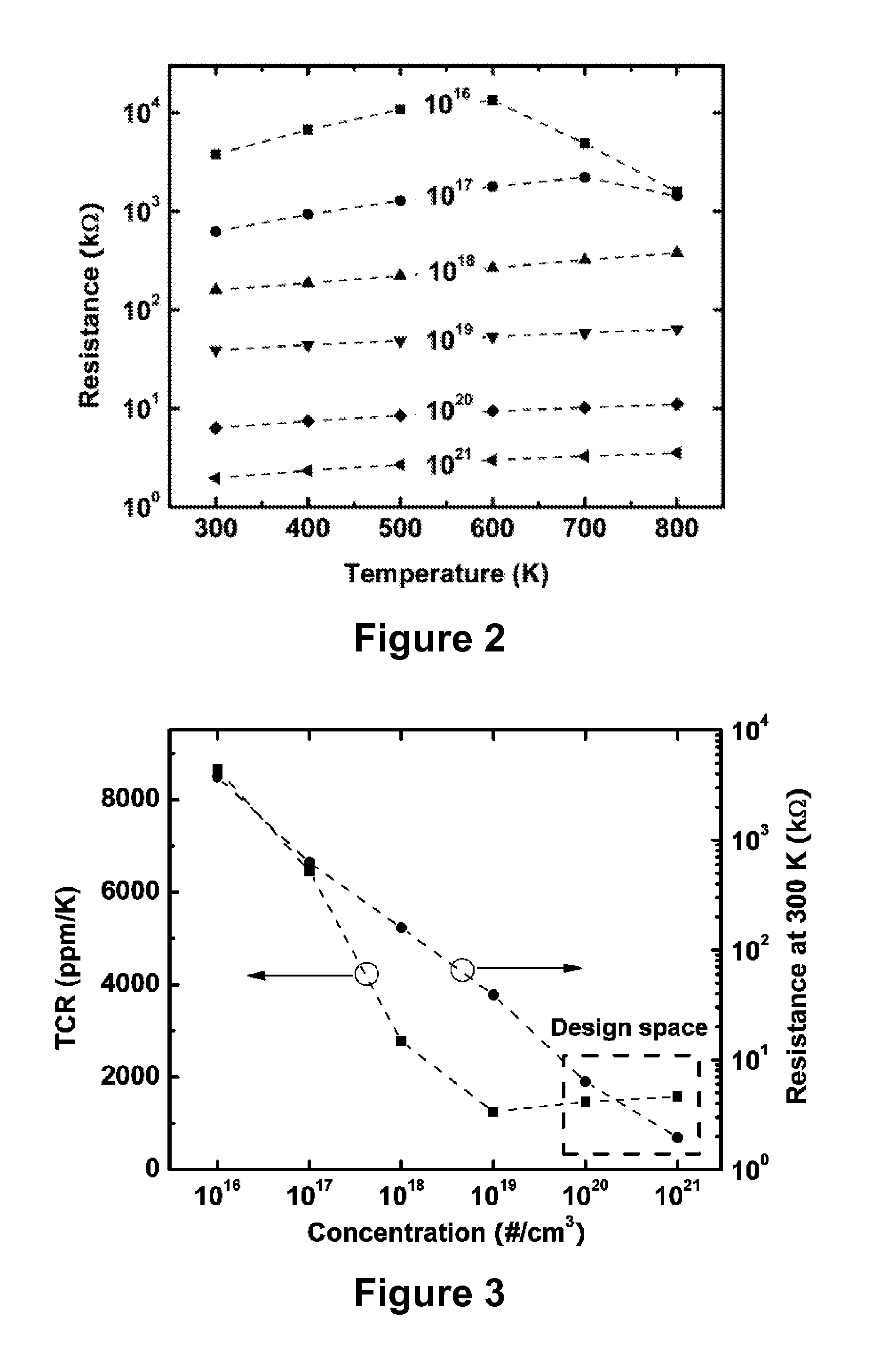
[0060]Design. In general, a silicon micro calorimeter shows better long-term stability than dielectric-metal calorimeters. FIG. 1 shows the design of a microfabricated calorimeter. A squared membrane exists at the center linked to the bulk silicon chip with four tethers. The length and width of the square membrane are each 100 μm and each tether is 10 μm wide and 222 μm long. Two tethers on the left are for heating and two tethers on the right for sensing. A serpentine heater track runs from a tether to another one through the island that will serve as a heater platform. Since only implanted and diffused resistors are employed, this design prevents any surface topology and achieves a planar surface. Doped silicon resistors have appreciable temperature coefficient of the resistance (TCR) compared to that of metals. Low-doped silicon can exhibit higher TCR than metal but its high resistance compromises ...

example 2

Differential Scanning Calorimeter Based on Suspended Membrane Single Crystal Silicon Micro Hotplate

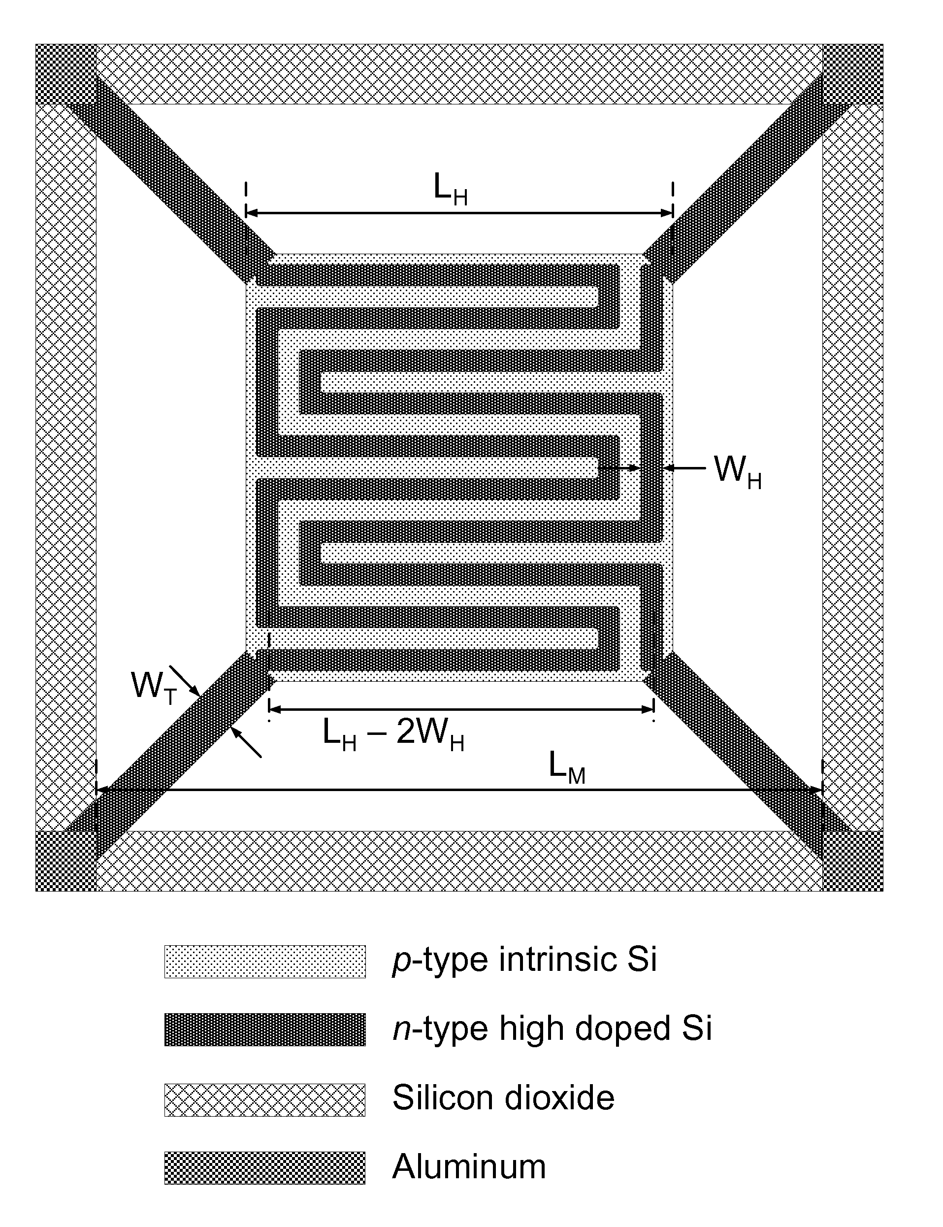
[0078]This example describes an array of single crystal silicon micro hotplates for differential scanning calorimetry (DSC). Heat transfer analysis considers the tradeoffs between heating and cooling rate, temperature uniformity, and measurement sensitivity, and determines the optimal design to be a suspended membrane micro hotplate with full backside release. Additionally considering the requirements of routine sample loading, the size of the square heater (LH) was chosen as 100 μm or 200 μm while the size of the suspended membrane was chosen as 400 μm. In the square heater region, two interdigitated serpentine doped silicon resistors were designed such that several operational configurations were possible. The hotplates exhibited very high heating efficiency of 36.7 K / mW with LH=100 μm and 18.3 K / mW with LH=200 μm while also having time constants on the order of 1 ms. Paraffin wax ...


PUM


Abstract

In one aspect, provided herein is a single crystal silicon microcalorimeter, for example useful for high temperature operation and long-term stability of calorimetric measurements. Microcalorimeters described herein include microcalorimeter embodiments having a suspended structure and comprising single crystal silicon. Also provided herein are methods for making calorimetric measurements, for example, on small quantities of materials or for determining the energy content of combustible material having an unknown composition.

Description

CROSS REFERENCE TO RELATED APPLICATION[0001]This application claims the benefit of and priority to U.S. Provisional Application 61 / 090,449, filed on Aug. 20, 2008, which is hereby incorporated by reference in its entirety.STATEMENT REGARDING FEDERALLY SPONSORED RESEARCH OR DEVELOPMENT[0002]This invention was made with United States governmental support under Award No. B568604 awarded by the United States Department of Energy. The United States government has certain rights in the invention.BACKGROUND OF THE INVENTION[0003]This invention is in the field of microcalorimetry. This invention relates generally to devices for performing calorimetry at small scales. In another aspect, the invention relates to methods of making calorimetric measurements.[0004]A calorimeter is a widely used analytical instrument that measures heat release or absorption by a sample under test. The main components in calorimeters are heating and temperature sensing elements such that the sample under test can ...

Claims


Application Information

Patent Timeline
IPC IPC(8): G01K17/00
CPCG01K17/006Y10S977/902G01N25/4813
Inventor KING, WILLIAM P.LEE, JUNGCHUL
Owner THE BOARD OF TRUSTEES OF THE UNIV OF ILLINOIS
Learn More