Bearing damper with spring seal

a damper and spring technology, applied in the direction of elastic bearings, rigid support of bearings, machines/engines, etc., can solve the problems of increasing specific fuel consumption (“sfc”), reducing sealing margins, increasing bearing cost and weight,

Active Publication Date: 2012-05-22
GENERAL ELECTRIC CO
View PDF43 Cites 46 Cited by
  • Summary
  • Abstract
  • Description
  • Claims
  • Application Information

AI Technical Summary

Problems solved by technology

The use of film dampers in gas turbine engines causes increased clearances for rotor blades and labyrinth seals leading to increased specific fuel consumption (“SFC”) and reduced sealing margins.
This is effective to limit clearances, but the spring structure increases the bearing cost and weight.

Method used


Image

  • Bearing damper with spring seal
  • Bearing damper with spring seal
  • Bearing damper with spring seal

Examples


Embodiment Construction

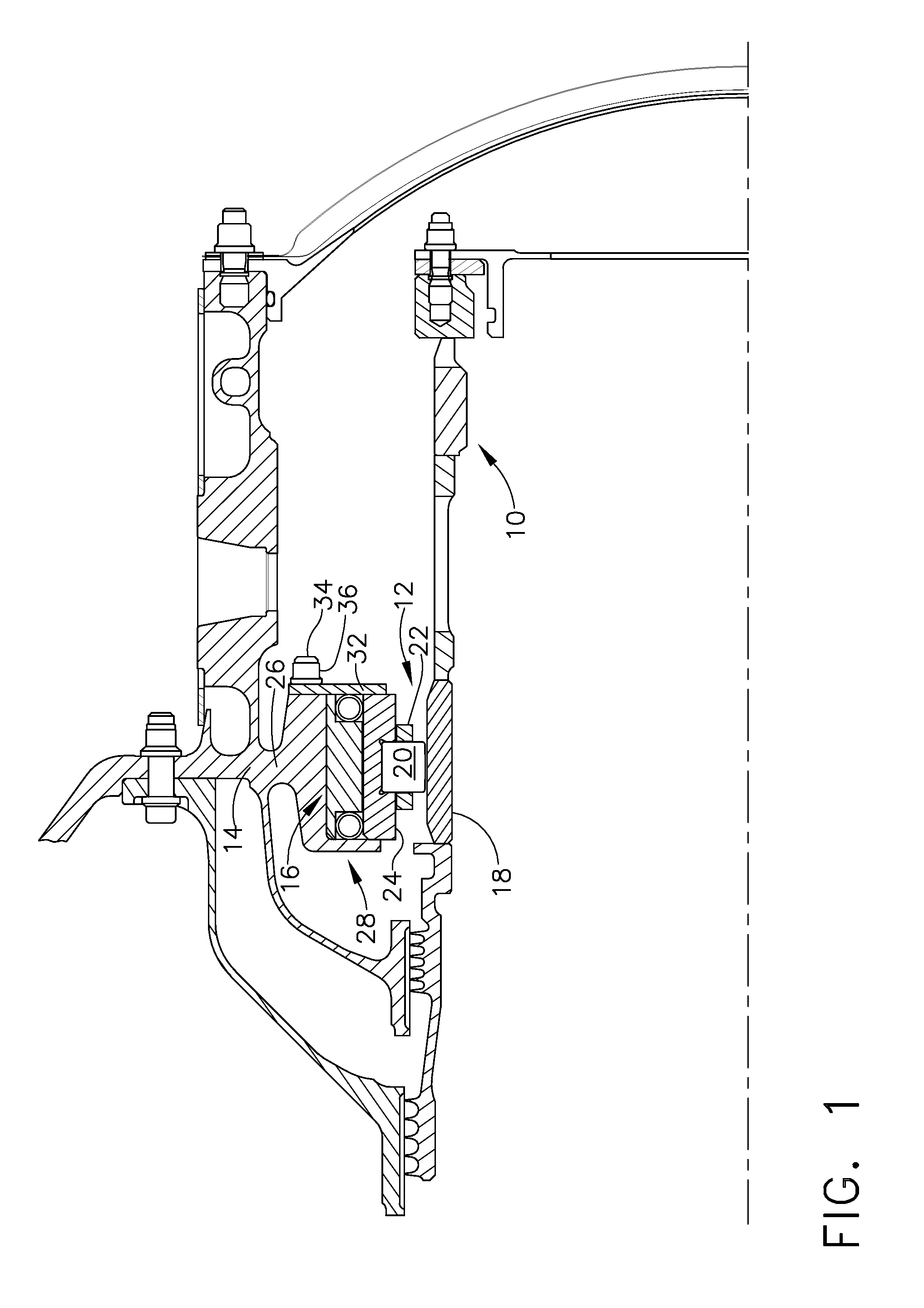
[0012]Referring to the drawings wherein identical reference numerals denote the same elements throughout the various views, FIG. 1 depicts a portion of an enclosed chamber or “sump” of a gas turbine engine, which in this case is a turboshaft engine. This is merely an example of a specific application, and the principles of the present invention are equally applicable to all kinds of turbomachinery such as turbojet, turboprop, and turbofan engines, as well as other types of machinery which use bearing dampers.

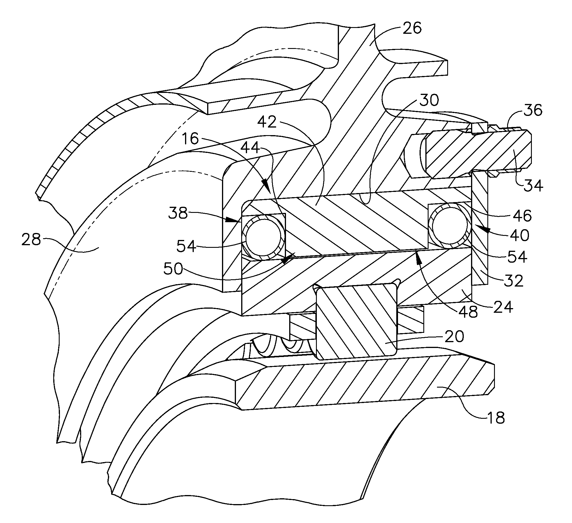
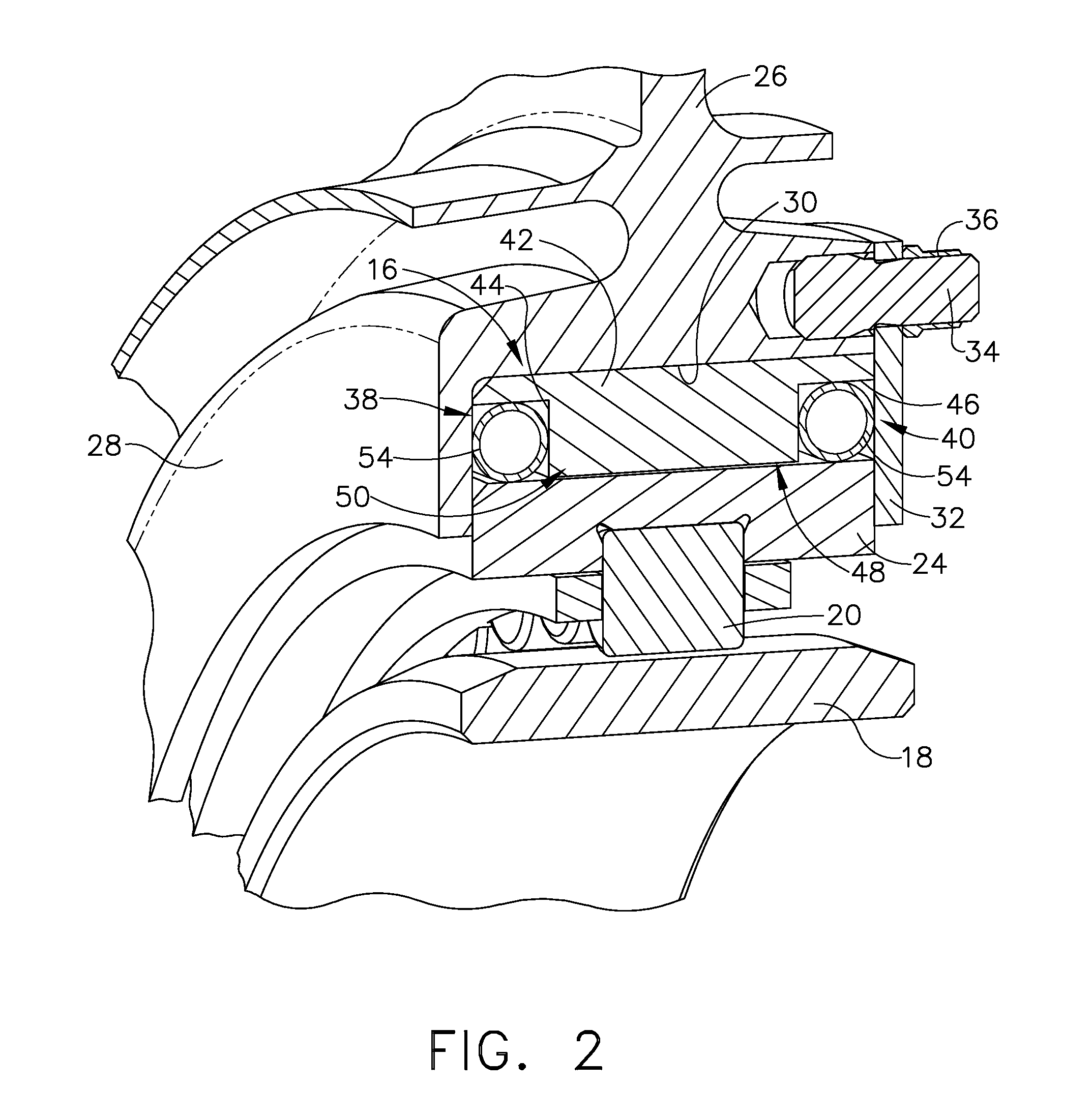
[0013]Within the sump, a shaft 10 of the engine is supported for rotation in a rolling-element bearing 12, in this case a roller bearing. A static annular frame member 14 surrounds the bearing 12. The bearing 12 is carried by the frame member 14 through a squeeze film bearing damper 16, which is described in more detail below. The bearing 12 includes an annular inner race 18 mounted on the shaft 10, a plurality of rollers 20 restrained by a cage 22, and an annular outer race 24....


PUM


Abstract

A bearing damper includes: (a) an annular sleeve having spaced-apart grooves formed in a radially-facing surface therein; (b) an annular bearing race received in the sleeve; and (c) a resilient seal ring disposed in each of the grooves, wherein the seal rings cooperate with the sleeve and a radially-facing surface of the bearing race to define a closed annular gap, and further wherein the seal rings are sized so as to urge the bearing race towards a coaxial position relative to the sleeve.

Description

FIELD OF THE INVENTION[0001]This invention relates generally to rotating bearings, and more particularly to squeeze film dampers for bearings associated with high speed turbomachinery.BACKGROUND OF THE INVENTION[0002]In a typical squeeze film shaft damper arrangement, a shaft with its associated rolling element bearing are permitted to have some limited radial motion in the supporting bearing housing. Ordinarily an annular outer race of a rolling element closely fits in an annular chamber in the support housing where two opposing closely adjacent circumferential surfaces of the housing and race define a thin annular squeeze film space into which an oil under pressure is introduced for damping action.[0003]The use of film dampers in gas turbine engines causes increased clearances for rotor blades and labyrinth seals leading to increased specific fuel consumption (“SFC”) and reduced sealing margins. The effectiveness of the damper is generally improved if the clearance is increased an...

Claims


Application Information

Patent Timeline
Patent Type & Authority Patents(United States)
IPC IPC(8): F16C27/00F16C33/76
CPCF01D25/164F16C27/04F16C27/066F16C2360/23F16C19/26F16C27/045
Inventor SINGH, ANANT PALSLUSHER, MICHAELSTORACE, ALBERT FRANKAUSTROW, JAMES C.METZ, TONY
Owner GENERAL ELECTRIC CO
Why Eureka
Try Eureka