Vacuum cleaning device

a vacuum cleaning and vacuum technology, applied in the direction of cleaning filter means, cleaning equipment, chemistry apparatus and processes, etc., can solve the problem of complicated design of the closing valve mechanism, and achieve the effect of effective filter cleaning

Active Publication Date: 2012-05-29
ALFRED KARCHER GMBH & CO KG
View PDF121 Cites 4 Cited by
  • Summary
  • Abstract
  • Description
  • Claims
  • Application Information

AI Technical Summary

Benefits of technology

[0008]The invention incorporates the idea that, by providing one or more sealing lines which are as long as possible but which delimit as small an area as possible, a strong, abruptly occurring external air stream can be provided within a very short time when the valve body is lifted away from the valve seat, so that the negative pressure abruptly drops on that side of the at least one filter which faces away from the dirt collection container, and external air flows through the filter in the countercurrent direction. The abrupt increase in pressure results in the filter being mechanically shaken and cleaned, it being possible for cleaning to be performed within a very short time. The total length of all sealing lines is selected to be considerably greater than the circumference of a circular area whose area corresponds to the area of the surface delimited by the sealing lines. The ratio between the square of the total length of all sealing lines and the size of the area delimited as a whole by the sealing lines is, according to the invention, at least 25 and is therefore at least twice the size as in the case of only one sealing line which surrounds a closed circular area whose circumference is defined by the sealing line. In the case of a circular area, the ratio of the square of the length of the sealing line to the size of the circular area has a value of approximately 12.5, specifically four times the number π (3.14).
[0035]The at least one filter can preferably be acted upon by external air by means of the at least one closing valve while maintaining a negative pressure in the mouth region of a suction hose which opens into the suction inlet. If the at least one closing valve is opened, the pressure on that side of the filter which faces away from the dirt collection container abruptly increases and is then reduced again. The abrupt increase in pressure effects effective cleaning of the filter but since it is immediately reduced again by the at least one suction turbine it does not lead to a complete interruption in the negative pressure in the mouth region of the suction hose which opens into the suction inlet. Instead, virtually continuous suction operation can be maintained.

Problems solved by technology

However, the supply of external air in each case only to a subregion of the filter requires a closing valve mechanism of complicated design.

Method used


Image

  • Vacuum cleaning device
  • Vacuum cleaning device
  • Vacuum cleaning device

Examples


Embodiment Construction

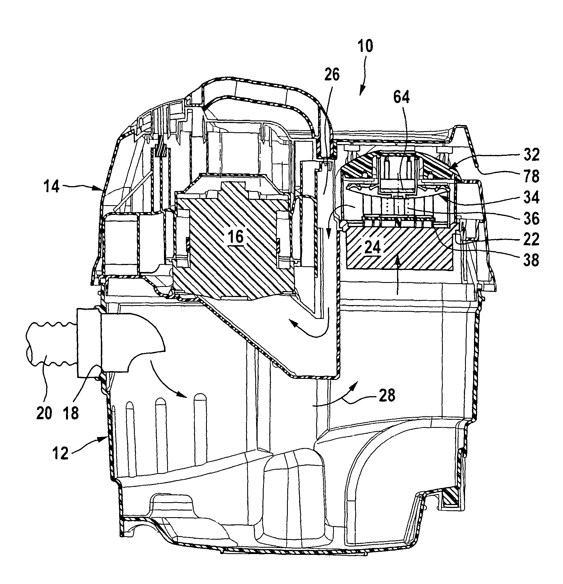
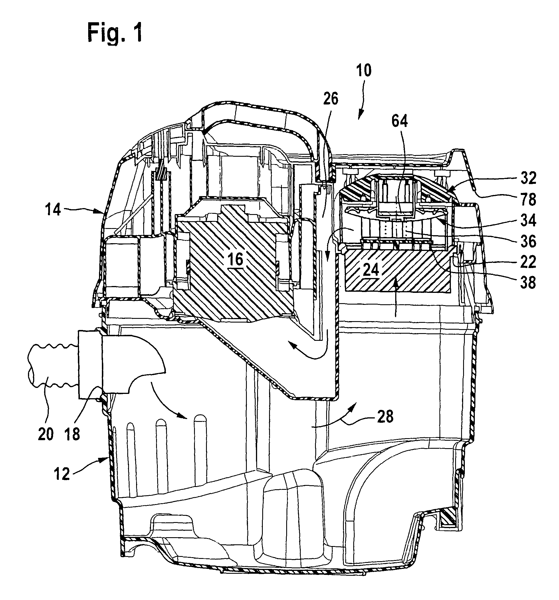
[0045]In the drawing, there is schematically illustrated a vacuum cleaning device in the form of a vacuum cleaner 10, comprising a lower part which forms a dirt collection container 12 and on which an upper part 14 which accommodates a suction unit 16 is fitted. The dirt collection container 12 has a volume of up to 80 l, preferably a volume of approximately 30 l to approximately 80 l. It comprises a suction inlet 18 to which a suction hose 20 can be connected at whose free end (not illustrated in the drawing in order to provide a better overview) a suction nozzle can be connected. As an alternative, provision may be made for the suction hose 20 to be connected to a working tool, for example a drilling unit or a milling unit, so that dust produced during operation of the working tool can be sucked away.

[0046]The upper part 14 forms a suction outlet 22 for the dirt collection container 12, a folded filter 24 being mounted at the suction outlet 22 and having connected to it a suction ...


PUM


Abstract

The invention relates to a vacuum cleaning device comprising a dirt collection container which has a suction inlet and is in flow connection with at least one suction unit via at least one filter and at least one suction line, and comprising at least one external air inlet which opens into the suction line downstream of the at least one filter and is adapted to be closed by means of at least one closing valve, the closing valve having a movable valve body which, in a closed position, bears against at least one valve seat so as to form one or more sealing lines, the at least one sealing line delimiting an area which, in the closed position of the closing valve, is acted upon by a differential pressure. In order to develop the vacuum cleaning device in such a way that the at least one closing valve is of structurally simple design and the at least one filter can be completely cleaned within a short period of time, the invention proposes that the square of the total length of all sealing lines is at least 25 times the total size of all areas which are delimited by the sealing lines and acted upon by a differential pressure.

Description

[0001]This application is a continuation of international application number PCT / EP2006 / 000672 filed on Jan. 26, 2006.[0002]The present disclosure relates to the subject matter disclosed in international application number PCT / EP2006 / 000672 of Jan. 26, 2006 and German application number 10 2005 017 568.6 of Apr. 11, 2005, which are incorporated herein by reference in their entirety and for all purposes.BACKGROUND OF THE INVENTION[0003]The invention relates to a vacuum cleaning device comprising a dirt collection container which has a suction inlet and is in flow connection with at least one suction unit via at least one filter and at least one suction line, and comprising at least one external air inlet which opens into the at least one suction line downstream of the at least one filter and is adapted to be closed by means of at least one closing valve, the at least one closing valve having a movable valve body which, in a closed position, bears against at least one valve seat so as...

Claims


Application Information

Patent Timeline
Patent Type & Authority Patents(United States)
IPC IPC(8): A47L9/10
CPCA47L9/20A47L9/0072
Inventor STEWEN, CHRISTIANHAEUSSERMANN, ULI
Owner ALFRED KARCHER GMBH & CO KG
Why Eureka
Try Eureka