Food storage device

Active Publication Date: 2012-05-29
TSENG MICHAEL
21 Cites 10 Cited by

AI-Extracted Technical Summary

Problems solved by technology

In addition, cellophane or saran wrap have been used to cover bowls or dishes enclosing food products therein; however, the thin film does not lend itself to stacking other items thereon.
The prior art does not address the need for a self-sealing lid that is capable of functioning with a variety ...

Method used

[0028]In order to enclose food within cavity 22, device 10 is placed over the food such that first member 20 rests upon component 24. Pressure is applied to surface 12 by a user's hand (not shown) such that first member 20 extends outwardly from a central axis. Structure 26 is then pressed inwardly toward cavity 22, thereby expelling air outwardly from in between the engagement of first member 20 and component 24. As such, the pressure within cavity 22 is reduced in relation to the atmospheric pressure and a suction seal is formed between first member 20 and component 24. In addition, as a result of the decreased pressure wi...

Benefits of technology

[0013]It is still a further object of the invention to provide a food storage device with an engaging mechanism that can provide a visual indication of proper engagement.
[0014]In keeping with the principles of the present invention, a unique food storage device is disclosed wherein the device is capable of engaging a variety of components, such as plates, bowls, trays, dishes and the like. In addition, by providing a substantially rigid body, the device lends itself to being stacked. One aspect of the preferred embodiment, has a substantially planar surface to allow stacking of multiple devices upon one another.
[0015]In another aspect of the preferred embodiment, a str...

Abstract

A device for storing food products in combination with a component, such as a plate or a bowl, such that a visual indication of secure engagement is provided and the device does not require a specific corresponding mating structure in order to provide an air-tight seal between said device and the component.

Application Domain

ClosuresTable equipments

Technology Topic

EngineeringStore food +2

Image

  • Food storage device
  • Food storage device
  • Food storage device

Examples

  • Experimental program(1)

Example

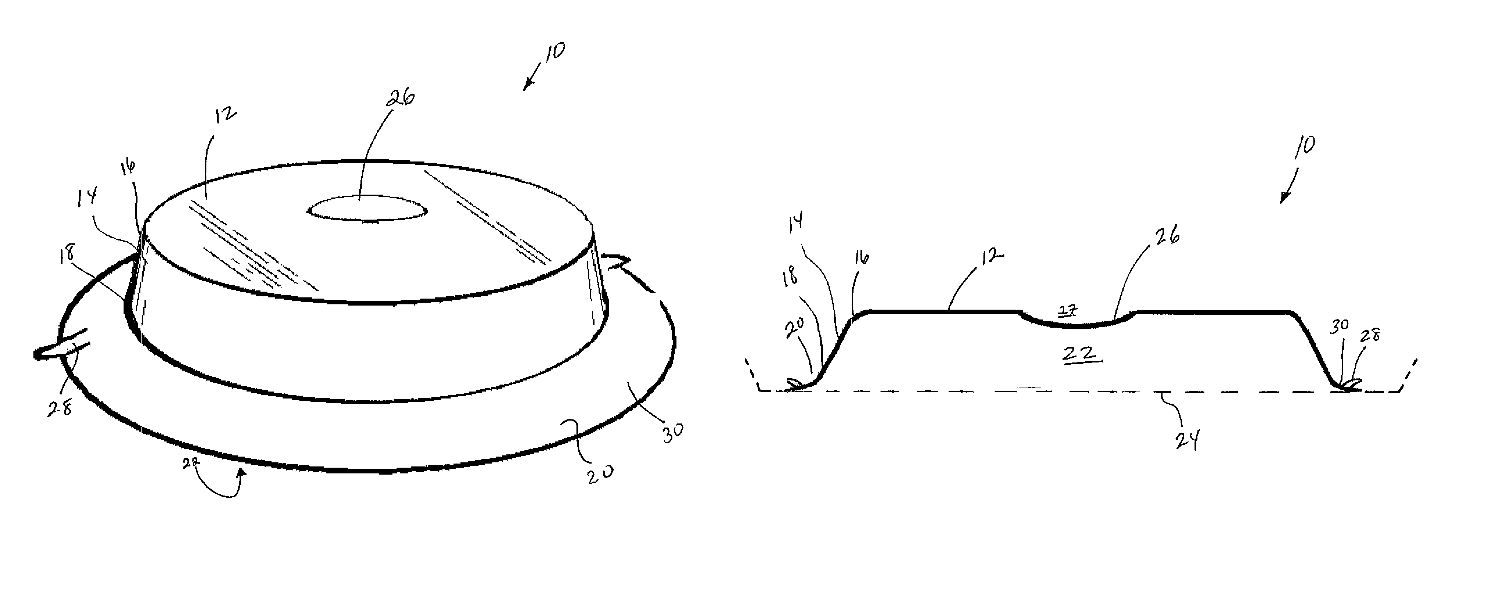
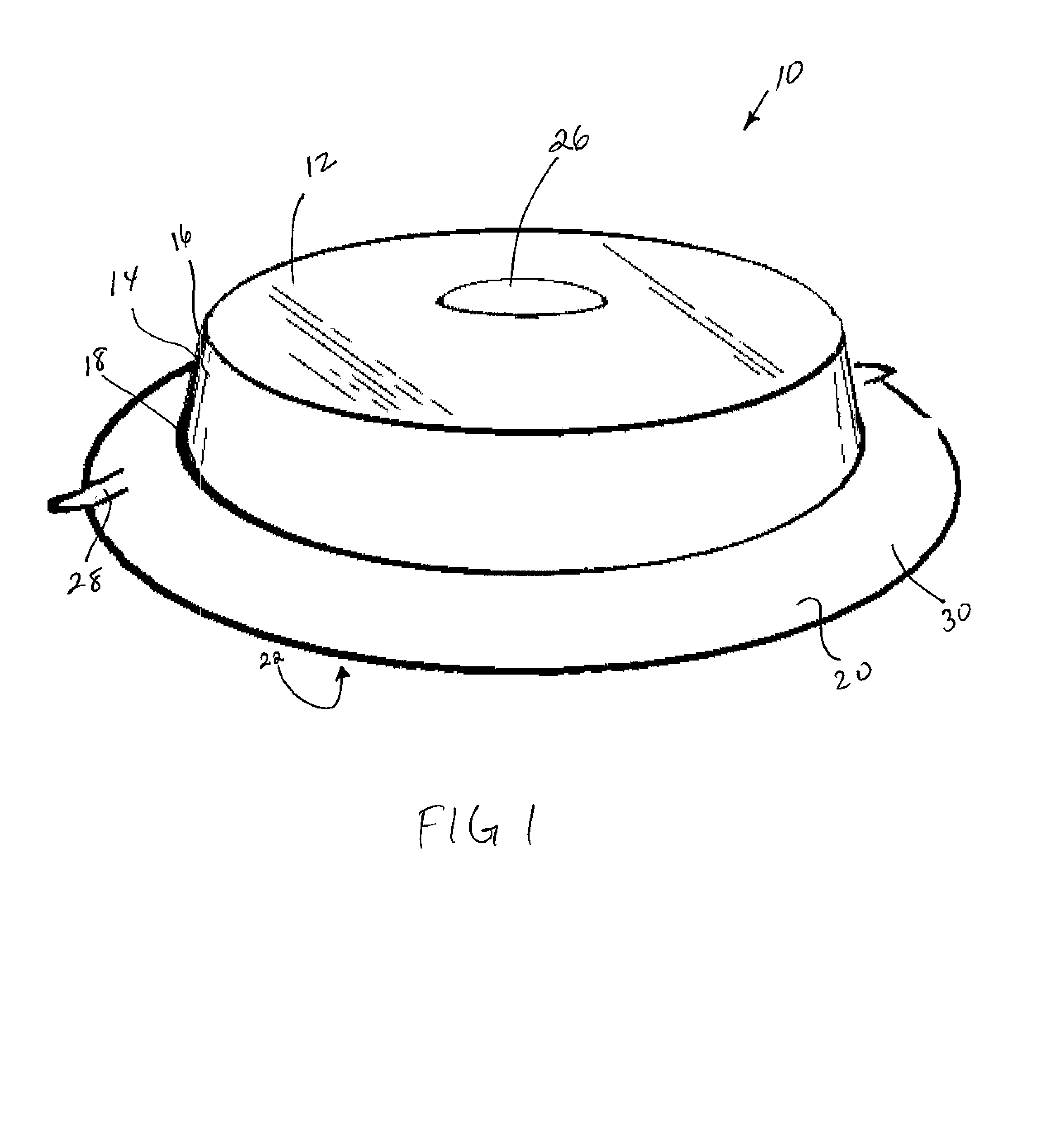
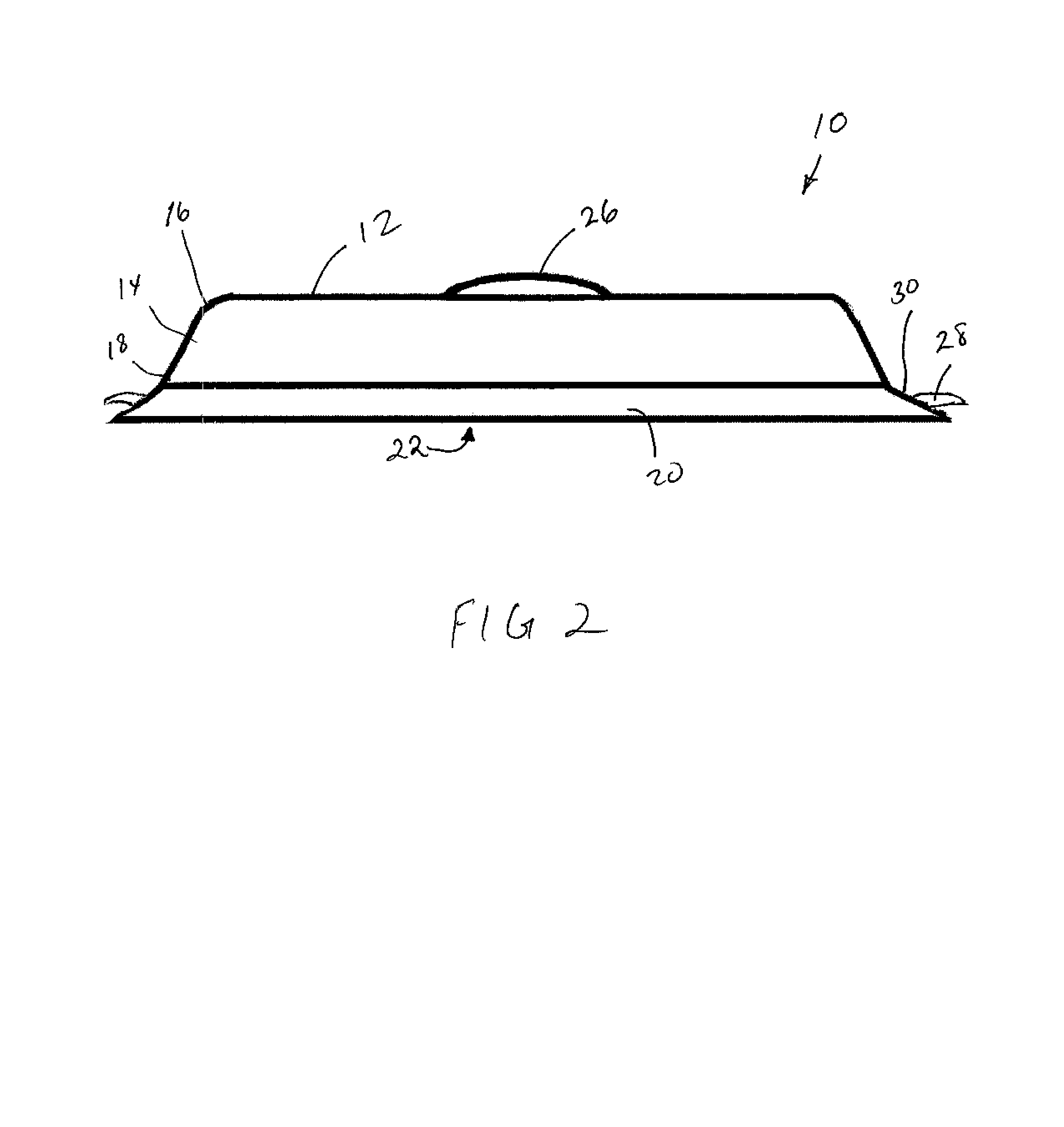
[0023]Referring now to the FIG. 1, a preferred embodiment of a food storage device generally designated by reference numeral 10 is illustrated. It is to be understood that although the invention is illustrated as having a preferred substantially cylindrical shape with a generally flat top, that other shapes may also be utilized without departing from the essence of the invention. For purposes of illustration, but not limitation, device 10 may be dome shaped or rectangular and designed to enclose food therein.
[0024]Device 10 has a surface 12 with a substantially peripheral wall 14 extending therefrom. Wall 14 has an upper end 16 and a lower end 18, whereby upper end 16 is in communication with surface 12 and lower end 18 is distal to the surface 12. In a preferred embodiment, surface 12 and wall 14 are substantially rigid and constructed of clear hard plastic or any other substantially rigid material that may be used in conjunction with a microwave oven. However, it is to be understood that surface 12 and wall 14 may also be opaque and constructed of any other substantially rigid material such as, glass, ceramics or the like.
[0025]Now also referring to FIGS. 2 through 4, a first member 20 extends from lower end 18 and is substantially flexible. In a preferred embodiment, first member 20 is constructed of synthetic rubber and is attached to lower end 18 via an extrusion of liquid plastic or adhesive. In the preferred embodiment described herein, first member 20 is substantially annular and extends circumferentially from lower end 18, but may be of any shape which corresponds with the shape of lower end 18. As such, the interior of device 10 defines a cavity 22 within which food may be stored.
[0026]Now referring specifically to FIG. 3, a component 24 acts as an engaging surface upon which first member 20 rests. Component 24 may be a dish, bowl, plate or tray or the like to which first member 20 can engage such that any food to be stored is maintained within cavity 22. However, component 24 does not have to be specifically designed to mate with first member 20. It is merely sufficient that component 24 have a substantially even region such that first member 20 may rest upon the even region.
[0027]A structure 26 is located on device 10 and is adapted to reduce pressure within cavity 22 by displacing air therefrom. In a preferred embodiment, an opening 27 is defined through surface 12 and structure 26 attaches to surface 12 and encloses opening 27. Structure 26 is attached to surface 12 via the application an extrusion of liquid plastic or adhesive at an outer periphery of structure 26 and the opening 27 defined by surface 12; however, it is to be understood that structure 26 may also be located on wall 14 or take the form of a removable pump (not shown) as is known in the art that displaces air by the use of a one-way valve located on first member 20. In the instant preferred embodiment, structure 26 is formed of flexible synthetic rubber, is substantially dome shaped and is resilient in nature.
[0028]In order to enclose food within cavity 22, device 10 is placed over the food such that first member 20 rests upon component 24. Pressure is applied to surface 12 by a user's hand (not shown) such that first member 20 extends outwardly from a central axis. Structure 26 is then pressed inwardly toward cavity 22, thereby expelling air outwardly from in between the engagement of first member 20 and component 24. As such, the pressure within cavity 22 is reduced in relation to the atmospheric pressure and a suction seal is formed between first member 20 and component 24. In addition, as a result of the decreased pressure within cavity 22, structure 26 is maintained in an inwardly shaped position, as illustrated in FIG. 3, and provides a visual indication to the user that the seal between first member 20 and component 24 is secure. Furthermore, a visual indication of a secure engagement is provided by the flattened nature of first member 20 as a result of the suction pressure applied during engagement. Such secure engagement between first member 20 and component 24 prevents air flow between cavity 22, wherein food is maintained, and the outside environment thereby delaying decomposition and prevents odor seepage or exchange during refrigeration.
[0029]In order to release the suction seal between first member 20 and component 24, at least one protrusion 28 is provided on an outer surface 30 such that protrusion 28 may be gripped by a user's fingers and an opposing force applied to disengage the seal between first member 20 and component 24. Upon disengagement of the seal between first member 20 and component 24, air is reintroduced into cavity 22 and structure 26 extends outwardly and to its pre-engaged position illustrated in FIGS. 1 and 2.
[0030]While the above description contains many specificities, these should not be construed as limitations on the scope of the invention, but rather as an exemplification of one preferred embodiment thereof. Many other variations are possible without departing from the essential spirit of this invention. Accordingly, the scope of the invention should be determined not by the embodiment illustrated, but by the appended claims and their legal equivalents.

PUM

no PUM

Description & Claims & Application Information

We can also present the details of the Description, Claims and Application information to help users get a comprehensive understanding of the technical details of the patent, such as background art, summary of invention, brief description of drawings, description of embodiments, and other original content. On the other hand, users can also determine the specific scope of protection of the technology through the list of claims; as well as understand the changes in the life cycle of the technology with the presentation of the patent timeline. Login to view more.

Similar technology patents

High density via and metal interconnect structures, and methods of forming the same

InactiveUS7939445B1minimal surfaceplanar surface
Owner:MARVELL INT LTD

Classification and recommendation of technical efficacy words

  • planar surface

High density via and metal interconnect structures, and methods of forming the same

InactiveUS7939445B1minimal surfaceplanar surface
Owner:MARVELL INT LTD
Why Eureka
Try Eureka