High density via and metal interconnect structures, and methods of forming the same

Inactive Publication Date: 2011-05-10
MARVELL INT LTD
View PDF4 Cites 19 Cited by
  • Summary
  • Abstract
  • Description
  • Claims
  • Application Information

AI Technical Summary

Benefits of technology

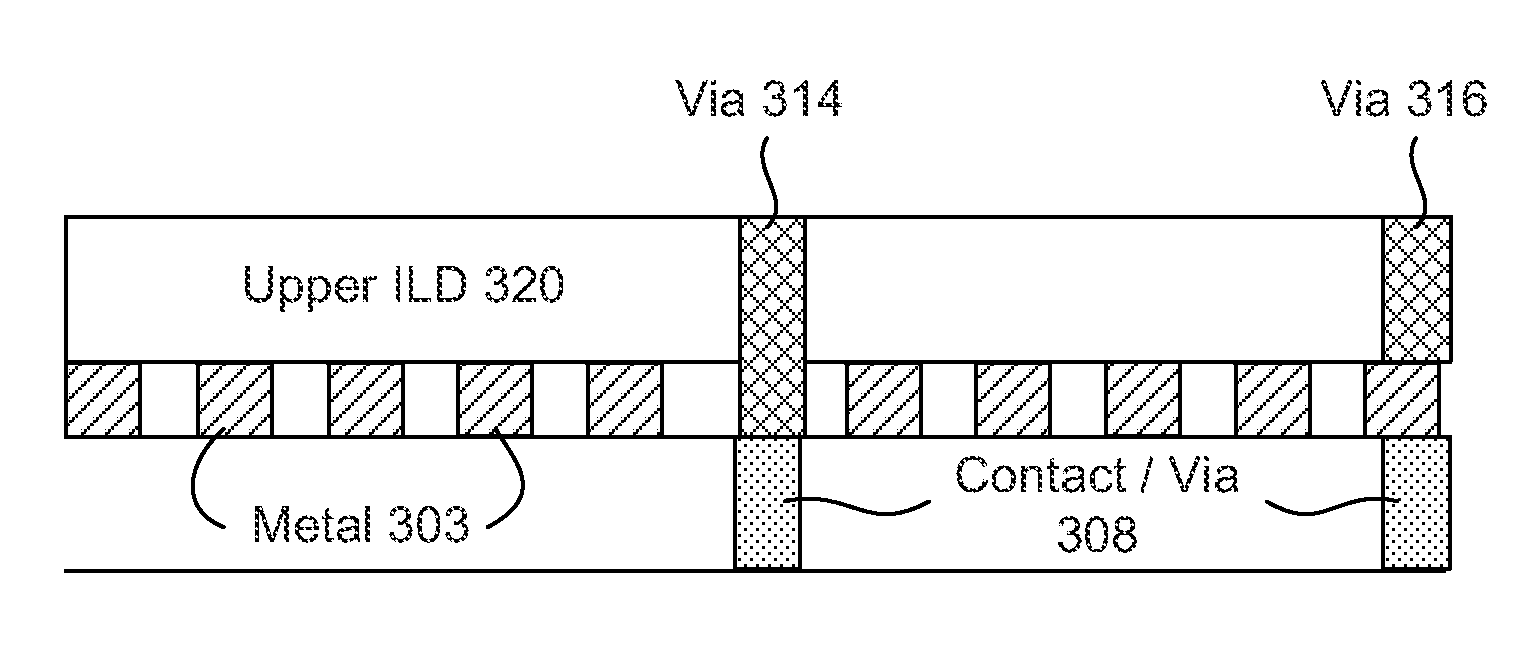
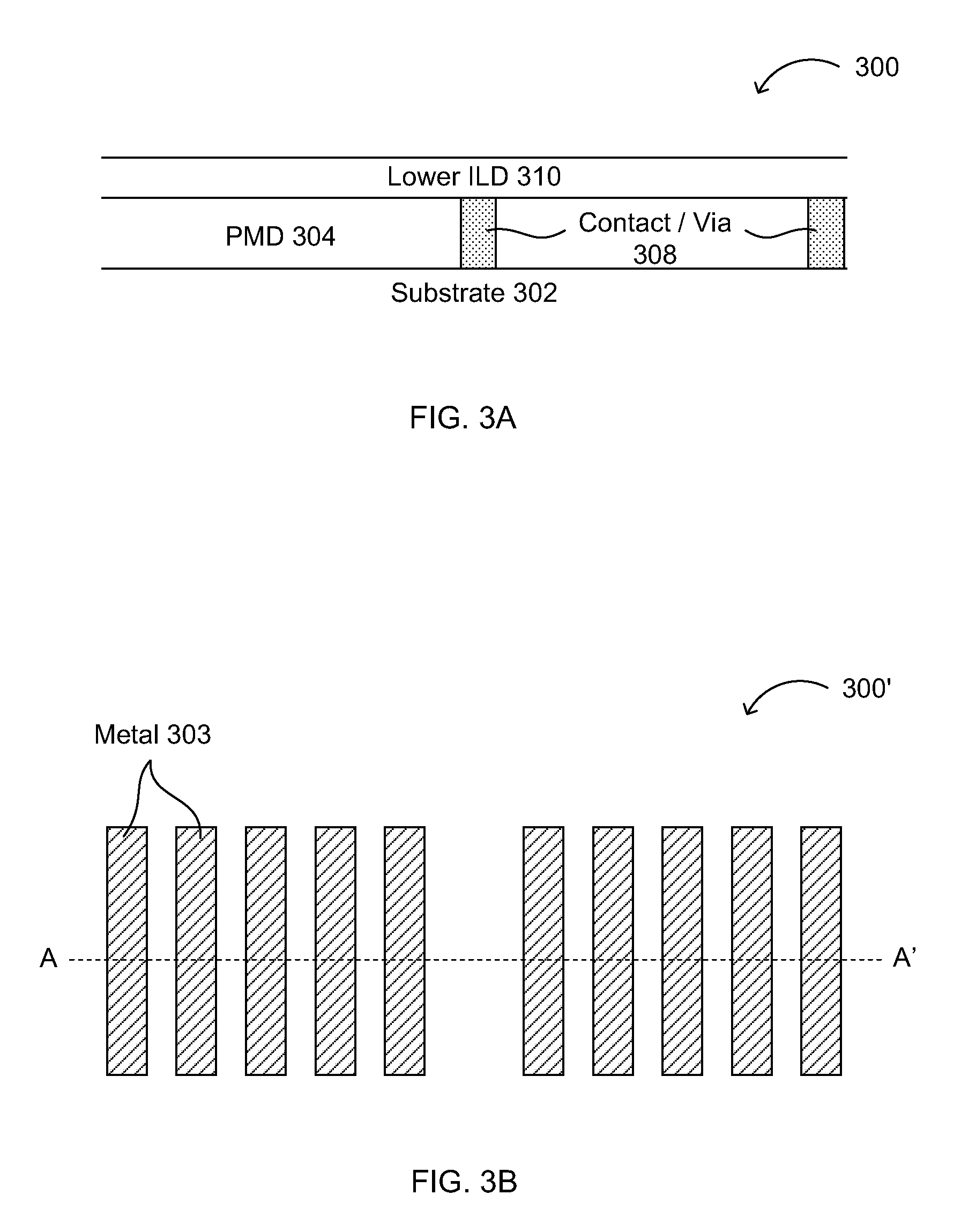
[0011]In another aspect, a metal interconnection structure may comprise a first pattern of metal lines, each of the metal lines in the first pattern having a minimum feature size in no more than one dimension in a layout view of the first pattern of metal lines; a first dielectric layer on or over the first pattern of metal lines, the first dielectric layer having a substantially planar horizontal upper surface; a plurality of first metal vias or contacts in the first dielectric layer, the first vias or contacts contacting a top surface of the first pattern of metal lines and a top surface of silicon structures or second vias or contacts below the first pattern of metal lines.
[0012]In various embodiments, the metal interconnection structure further comprises the second vias or contacts below the first pattern of metal lines, and the first vias or contacts contact the top surface of the second vias or contacts. Also, the metal interconnection structure may further comp

Problems solved by technology

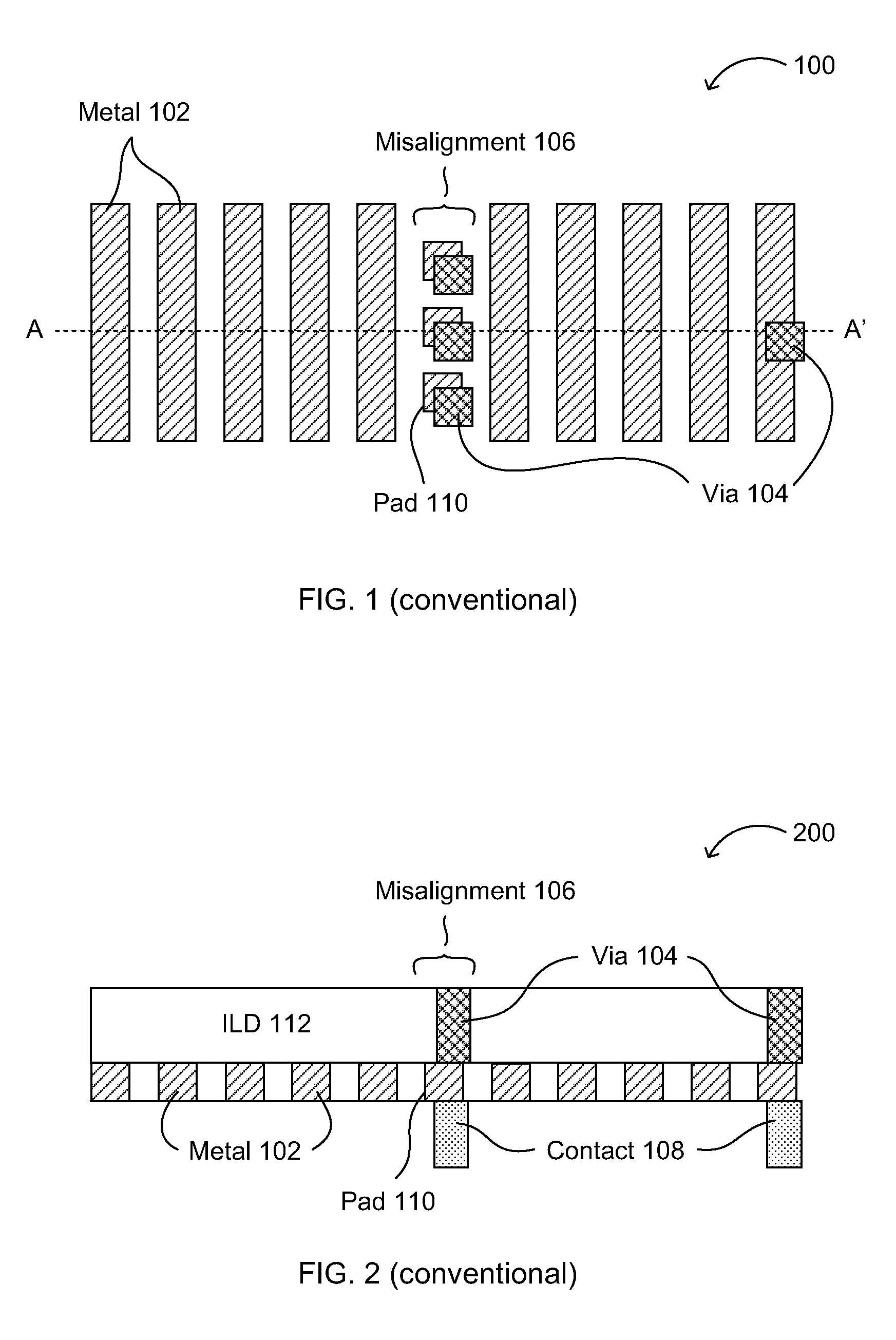
For sub-100 nm advanced semiconductor processes in particular, contact/via resistance due to misalignment involving metal features of such minimum feature size may be a serious concern.
Even with processing techniques that may help improve reliability, such as optical proximity correction (O

Method used


Image

  • High density via and metal interconnect structures, and methods of forming the same
  • High density via and metal interconnect structures, and methods of forming the same
  • High density via and metal interconnect structures, and methods of forming the same

Examples


Example

[0027]Reference will now be made in detail to example embodiments, which are illustrated in the accompanying drawings. While the invention will be described in conjunction with example embodiments, the invention is not intended to be limited to these embodiments. On the contrary, the invention is intended to cover alternatives, modifications and equivalents that may be included within the scope of the invention as defined by the appended claims. Furthermore, in the following detailed description, numerous specific details are set forth in order to provide a thorough understanding of the disclosure, however, the present invention may be practiced without these specific details. In other instances, well-known methods, procedures, components, and circuits have not been described in detail so as not to unnecessarily obscure aspects of the disclosure.

[0028]For the sake of convenience and simplicity, the terms “node(s),”“input(s)” and “output(s)” may be used interchangeably, as may the te...


PUM


Abstract

Methods and structures for interconnects in semiconductor devices are described. A method of forming a mask pattern for a metal layer in an interconnect can include searching a layout for a metal feature with a predetermined size and an interconnect layer aligned thereto, removing the metal feature from the layout to form a modified layout, and reforming the mask pattern using the modified layout. The metal interconnect may include a first pattern of metal lines, each having a minimum feature size in a layout view in no more than one dimension; a dielectric layer on or over the first pattern of metal lines, having a substantially planar horizontal upper surface; and vias or contacts in the dielectric layer, the vias or contacts contacting a top surface of the first pattern of metal lines and a top surface of silicon structures, vias, or contacts below the first pattern of metal lines.

Description

RELATED APPLICATIONS[0001]This application claims the benefit of U.S. Provisional Application No. 60 / 895,296, filed on Mar. 16, 2007, incorporated herein by reference in its entirety.FIELD[0002]The present disclosure generally relates to the field of semiconductor devices. More specifically, embodiments of the present invention pertain to methods and structures for interlayer interconnects within semiconductor devices.DISCUSSION OF THE BACKGROUND[0003]Manufacturing features of semiconductor devices at a minimum feature size may increasingly be necessary to achieve product competitiveness, which is often dependent on device density and overall chip size in modern semiconductor processing. For sub-100 nm advanced semiconductor processes in particular, contact / via resistance due to misalignment involving metal features of such minimum feature size may be a serious concern. Even with processing techniques that may help improve reliability, such as optical proximity correction (OPC), a f...

Claims


Application Information

Patent Timeline
IPC IPC(8): H01L21/4763
CPCH01L21/76838H01L21/76816
Inventor SUTARDJA, PANTASWU, ALBERTLEE, WINSTONLEE, PETERWEI, CHIEN-CHUANCHANG, RUNZI
Owner MARVELL INT LTD
Why Eureka
Try Eureka