Subminiature imaging optical system

a sub-miniature and optical system technology, applied in optics, instruments, lenses, etc., can solve the problems of affecting the quality of optical images, and reducing the degree of freedom of design, so as to prevent the degradation of color definition and correct the chromatic aberration of lenses.

Active Publication Date: 2010-06-22
SAMSUNG ELECTRO MECHANICS CO LTD
View PDF4 Cites 3 Cited by
  • Summary
  • Abstract
  • Description
  • Claims
  • Application Information

AI Technical Summary

Benefits of technology

[0010]An aspect of the present invention provides a subminiature imaging optical system capable of effectively correcting chromatic aberration of lenses to prevent degradation of color definition.
[0011]An aspect of the present invention also provides a subminiature imaging optical system in which lenses have minimum aspherical surfaces to require less precise machining, and each of the lenses has power adequately adjusted to enhance image quality.

Problems solved by technology

In order to satisfy miniaturization and low cost, the imaging optical system mounted on a small device such as a mobile phone needs to have lenses of as small a number as possible, but this restricts a degree of freedom in designing and undermines the optical capabilities.
This construction may satisfy high pixel requirements, but degrades color definition due to increase in chromatic aberration.
Besides, this renders the imaging optical system hardly miniaturizable enough to suit consumer's needs.

Method used


Image

  • Subminiature imaging optical system
  • Subminiature imaging optical system
  • Subminiature imaging optical system

Examples


first embodiment

[0053]Table 1 below shows numerical values according to a first embodiment of the present invention.

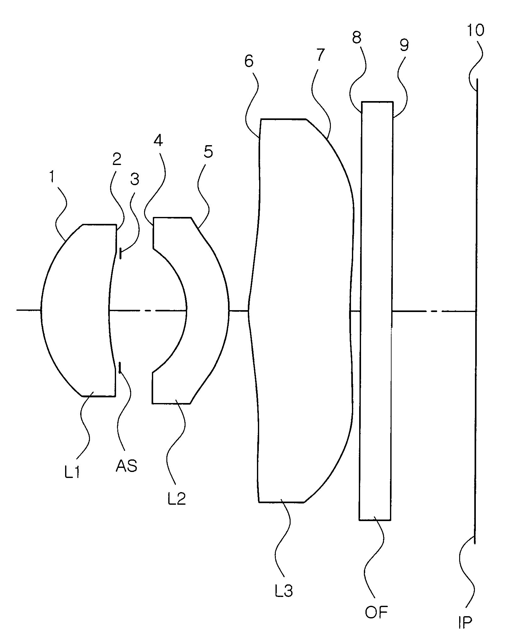
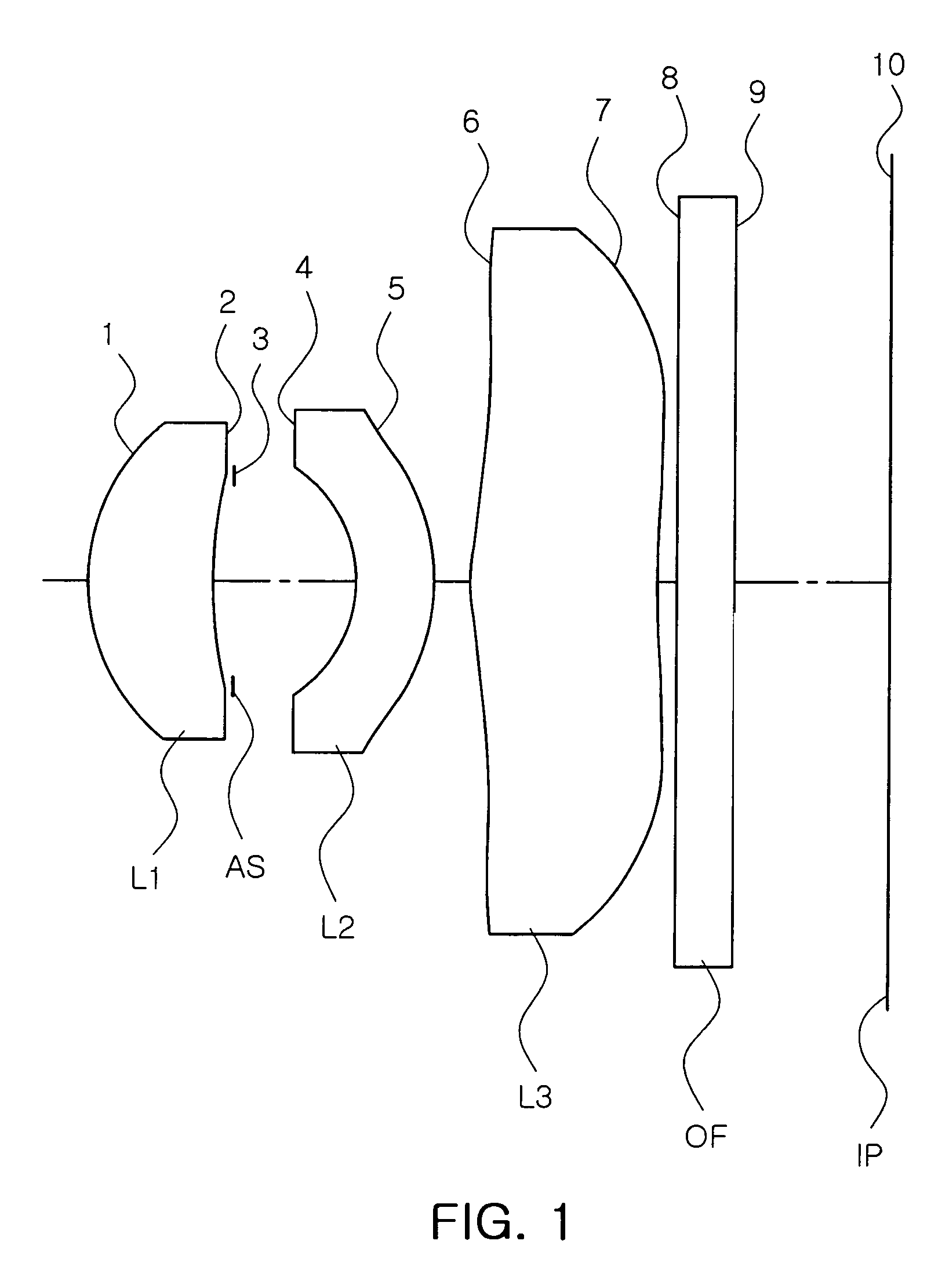
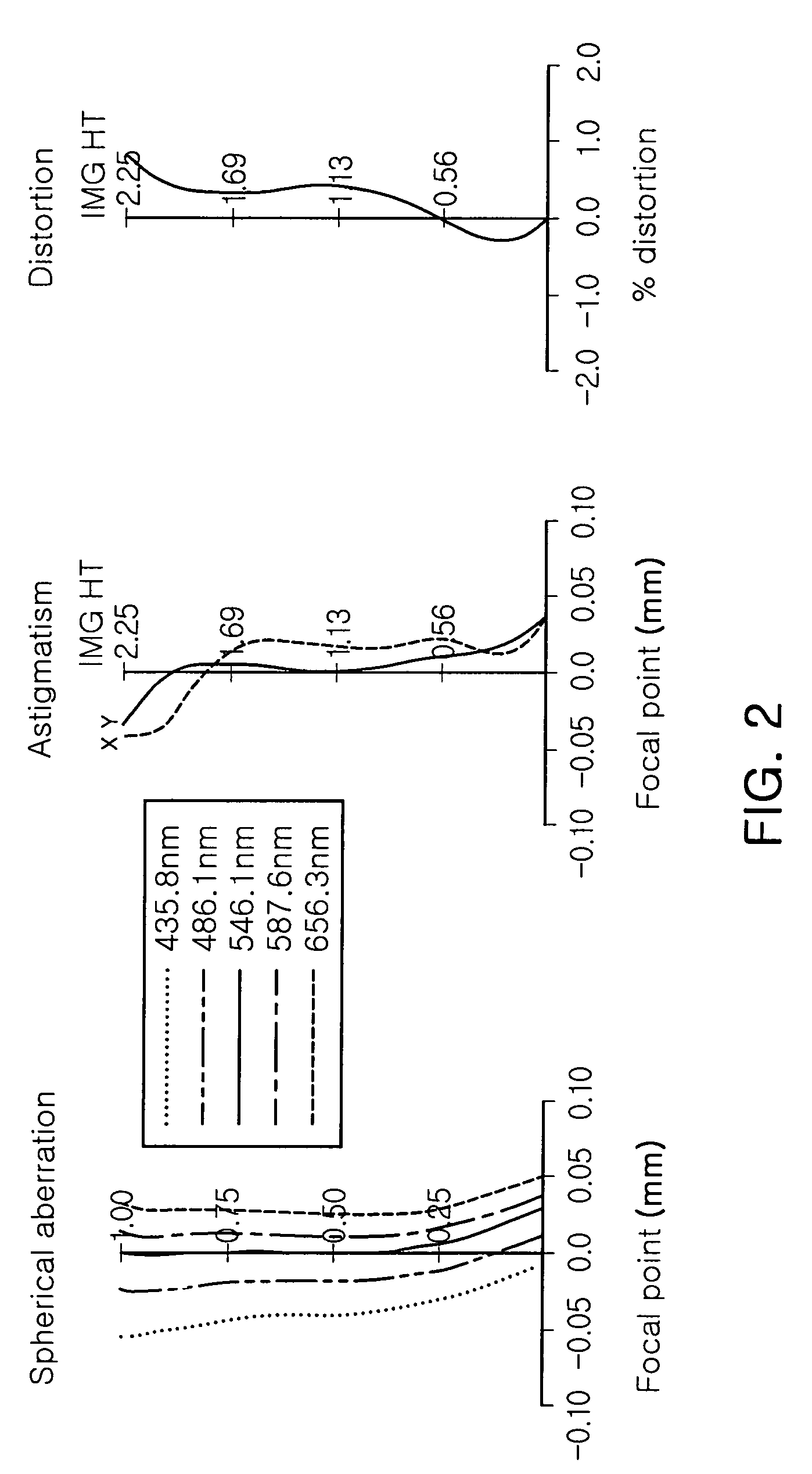
[0054]FIG. 1 is a view illustrating a lens arrangement of the subminiature imaging optical system according to the first embodiment of the present invention, and FIGS. 2A to 2C show aberrations of the embodiment shown in Table 1 and FIG. 1. FIG. 3 is a graph illustrating MTF characteristics shown in FIG. 1.

[0055]Here, the MTF depends on a spatial frequency of a cycle per millimeter and is defined by the following Equation 2 between a maximum intensity (Max) and a minimum intensity (Min) of light.

MTF=(Max−Min) / (Max+Min)  Equation 2

[0056]That is, MTF is most ideal when 1 and a smaller MTF deteriorates resolution.

[0057]In the first embodiment, an F number Fno is 2.8, an angle of view is 65.0 degrees, a total length from the object-side surface 1 of the first lens L1 to the image plane IP is 4.2 mm, and an effective focal length f is 3.56 mm. Also, a focal length f1 of the first lens L1 i...

second embodiment

[0062]Table 3 below shows numerical values according to a second embodiment of the present invention. FIG. 4 is a view illustrating a lens arrangement of the subminiature imaging optical system according to the second embodiment of the present invention, and FIGS. 5A to 5C show aberrations of the embodiment shown in Table 3 and FIG. 4. FIG. 6 is a graph illustrating MTF characteristics of the embodiment shown in FIG. 4.

[0063]In the second embodiment, an F number Fno is 2.7, an angle of view is 65.0 degrees, a total length TL from the object-side surface 1 of the first lens L1 to the image plane IP is 4.30 mm, and an effective focal length f is 3.53 mm. Also, a focal length f1 of the first lens L1 is 2.80 mm, a focal length of the second lens L2 is −8.26 mm, a focal length f3 of the third lens L3 is 14.30 mm, a maximum thickness Tmax of the third lens L3 within an effective aperture is 3.99 mm, and a minimum thickness Tmin of the third lens L3 within an effective aperture is 1.07 mm....


PUM


Abstract

There is provided a subminiature imaging optical system utilizing only three sheets of lenses having positive, negative and positive refractive powers, respectively. The subminiature imaging optical system comprising, sequentially from an object side: a first lens having a meniscus shape with a convex object-side surface, the first lens having at least one aspherical surface and positive refractive power; a second lens having a meniscus shape with a convex image-side surface, the second lens having at least one spherical surface and negative refractive power; and a third lens having both surfaces formed of an aspherical surface and having positive refractive power.

Description

CROSS-REFERENCE TO RELATED APPLICATIONS[0001]This application claims the priority of Korean Patent Application No. 2007-25981 filed on Mar. 16, 2007, in the Korean Intellectual Property Office, the disclosure of which is incorporated herein by reference.BACKGROUND OF THE INVENTION[0002]1. Field of the Invention[0003]The present invention relates to a subminiature imaging optical system, and more particularly, to a subminiature imaging optical system installed in a mobile communication terminal and a personal digital assistant (PDA) or utilized in a surveillance camera and a digital camera.[0004]2. Description of the Related Art[0005]In general, mobile communication terminals had only functions of basic communication at their incipient stage. However, with increased use, the mobile communication terminals are required to have diversified functions ranging from photographing to image transmission and video communication, continuously evolving in their functions and services. Recently,...

Claims


Application Information

Patent Timeline
Patent Type & Authority Patents(United States)
IPC IPC(8): G02B9/14G02B3/02G02B9/00
CPCG02B13/18G02B9/14G02B13/0035
Inventor KIM, JIN JONGKIM, YOUNG GIJO, YONG JOO
Owner SAMSUNG ELECTRO MECHANICS CO LTD
Why Eureka
Try Eureka