Hidden flexure ultra planar optical routing element

a technology of ultra-planar optical routing and hidden flexure, applied in the field of micro-electricalmechanical systems, can solve the problems of complex compound process, difficult and expensive scaling of dwdm network using sonet/sdh technology, and explosion of global bandwidth demand

Inactive Publication Date: 2006-03-28
ALTERA CORP
View PDF33 Cites 8 Cited by
  • Summary
  • Abstract
  • Description
  • Claims
  • Application Information

AI Technical Summary

Benefits of technology

[0016]In one particular aspect, the underlying edges of the flexure assembly and beam layer are configured to simultaneously contact the base layer upon rotation of the beam layer. In this manner, the underlying edges of two or more layers provide a stable multi-point landing system for the beam layer. Further, the beam layer preferably has a substantially planar upper surface when the underlying edges are in contact with the base layer.

Problems solved by technology

The Internet and data communications are causing an explosion in the global demand for bandwidth.
This makes it difficult and expensive to scale DWDM networks using SONET / SDH technology.
This compound process is complex, very expensive, decreases system reliability and complicates system management.
The OXC in particular is a technical challenge.
Opto-mechanical switches, which offer acceptable optical specifications are too big, expensive and unreliable for widespread deployment.
However, MEMS also have difficulties to overcome.
For example, voltages needed to rotate the micromirror often are larger than desired, resulting in distortion of the mirror shape.

Method used


Image

  • Hidden flexure ultra planar optical routing element
  • Hidden flexure ultra planar optical routing element
  • Hidden flexure ultra planar optical routing element

Examples


Embodiment Construction

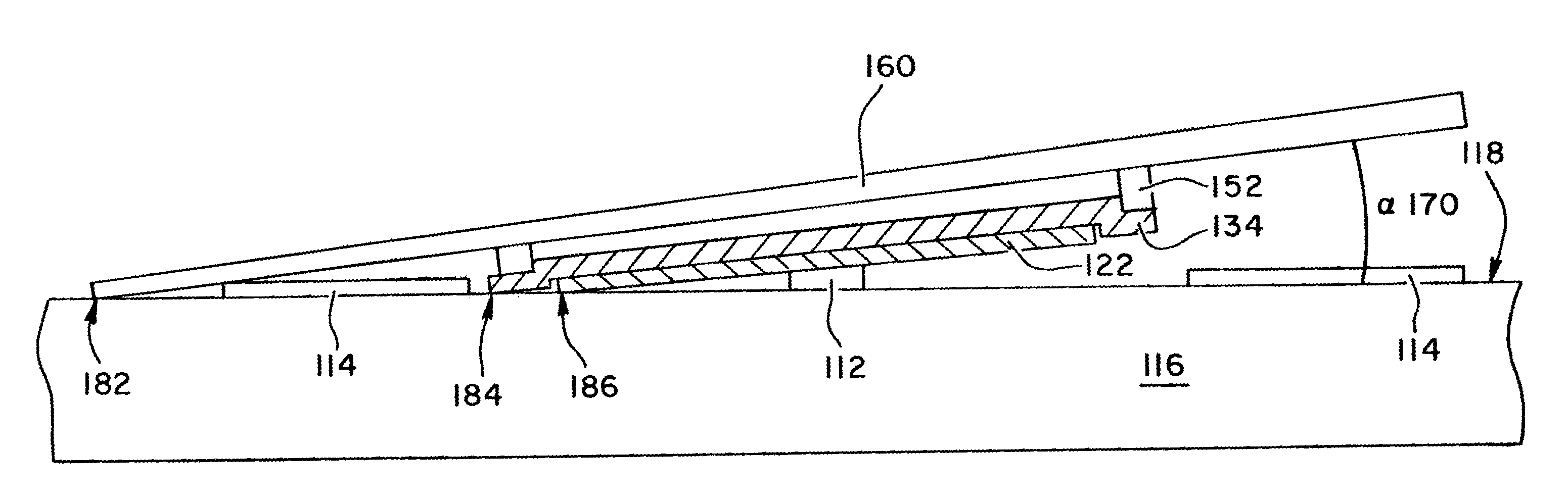
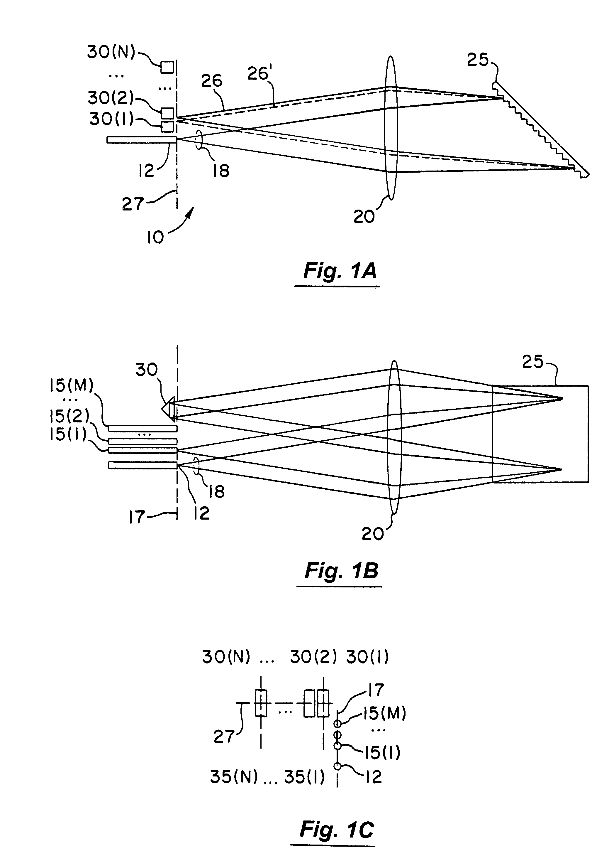
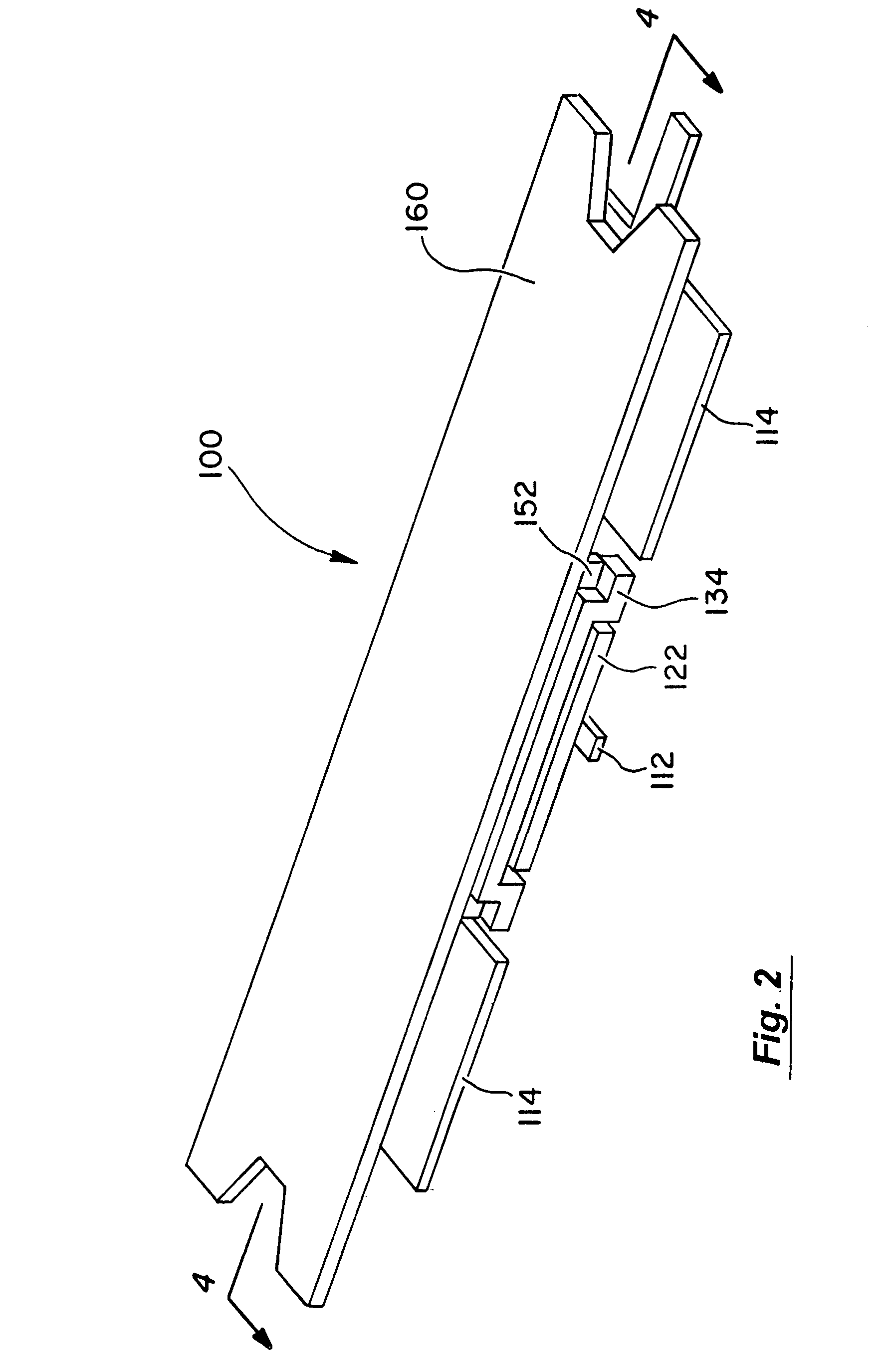
[0031]The general functionality of a wavelength router is to accept light having a plurality of spectral bands (i.e., “N” spectral bands) at an input port, and selectively direct subsets of the spectral bands to desired ones of a plurality of output ports (i.e., “M” output ports). The routers may include dynamic switching where the routing mechanism includes one or more routing elements whose state can be dynamically changed in the field to effect switching. The routers may also include static embodiments in which the routing elements are configured at the time of manufacture or under circumstances where the configuration is intended to remain unchanged during prolonged periods of normal operation.

[0032]The routers may include a dispersive element, such as a diffraction grating or a prism, which operates to deflect incoming light by a wavelength-dependent amount. Different portions of the deflected light are intercepted by different routing elements. Although the incoming light coul...


PUM


Abstract

The present invention provides improved MEMS devices and methods for use with fiber-optic communications systems. In one embodiment, an apparatus for steering light has a beam layer (160) with a reflective surface. The device uses a multi-layer electrode stack underlying the beam layer to rotate the beam layer into a desired position. Additionally, an underlying rotation and support structure provides a stable platform for the beam layer when the device is activated. In one embodiment, the underlying structure provides a multi-point landing system to maintain a generally flat beam layer upper surface when the device is activated.

Description

CROSS REFERENCE TO RELATED APPLICATIONS[0001]This application is a continuation of Ser. No. 09 / 859,069, and relies on the benefit of the filing date of, now U.S. Pat. No. 6,608,712 B2, filed on May 15, 2001, the entire disclosure of which is incorporated herein by reference for all purposes.BACKGROUND OF THE INVENTION[0002]This invention relates generally to the field of micro-electrical-mechanical systems (MEMS), and in particular, to improved MEMS devices and methods of making same for use with fiber-optic communications systems.[0003]The Internet and data communications are causing an explosion in the global demand for bandwidth. Fiber optic telecommunications systems are currently deploying a relatively new technology called dense wavelength division multiplexing (DWDM) to expand the capacity of new and existing optical fiber systems to help satisfy this demand. In DWDM, multiple wavelengths of light simultaneously transport information through a single optical fiber. Each wavel...

Claims


Application Information

Patent Timeline
Patent Type & Authority Patents(United States)
IPC IPC(8): G02B26/00H01L41/04G02B26/08
CPCG02B26/0841
Inventor MICHALICEK, M. ADRIAN
Owner ALTERA CORP
Why Eureka
Try Eureka