Device for attaching an aircraft engine

a technology for aircraft engines and components, applied in the direction of machine supports, transportation and packaging, other domestic objects, etc., can solve the problems of high time-consuming and costly penalties, and achieve the effect of improving the transmission of forces

Active Publication Date: 2012-05-29
AIRBUS OPERATIONS (SAS)
View PDF14 Cites 4 Cited by
  • Summary
  • Abstract
  • Description
  • Claims
  • Application Information

AI Technical Summary

Benefits of technology

[0016]Thus, the invention provides the advantage of housing the barrel nut outside the rigid box-forming structure, which makes it easily accessible for an operator who wishes to carry out routine inspections or a replacement of this same barrel nut. The aforementioned operations may therefore be widely optimized as compared to those encountered in the prior art, which is advantageously expressed by a gain in terms of time and ease of intervention for the operator.
[0018]Preferably, the barrel nut is entirely located beyond an end of a bore of the main fitting crossed by the fixing peg, in a longitudinal direction of this same fixing peg. In other words, the barrel nut housed in the fixing peg is located with sufficient clearance away from the main fitting so that it may be removed from the fixing peg, without requiring the removal of the main fitting located on the outside relatively to the rigid box-forming structure. Indeed, in such a case, it is then only sufficient to remove the screw and the bell-shaped supporting washer in order to be able to have direct access to the barrel nut, which may then be easily removed from its associated housing by sliding.
[0021]Further, the secondary fixing portion also passes through a sole of one of the transverse ribs of the rigid structure, against which the nut is pressed. By integrating one of the transverse ribs into the assembly, the maintaining of the main fitting relatively to the rigid structure may be reinforced, and better transmission of the forces may be provided from the engine and directly towards the wing or the rear portion of the fuselage of the aircraft.

Problems solved by technology

If the use of barrel nuts proves to be interesting because of the high safety which they provide, a drawback related to this use resides in the fact that these nuts are generally located inside the rigid structure forming a structure box, thereby making them accessible with difficulty during the numerous inspection calls which this type of nut requires.
Thus, it is clear that the operations for inspections and for replacing barrel nuts located inside the structure box are clearly not optimized, and consequently very penalizing in terms of time.
Of course, such screw / barrel nut assemblies may also be encountered for fixing the main fittings of the engine attachment members on a given supporting spar of the rigid structure, which even further emphasizes the drawbacks mentioned above.

Method used


Image

  • Device for attaching an aircraft engine
  • Device for attaching an aircraft engine
  • Device for attaching an aircraft engine

Examples


Embodiment Construction

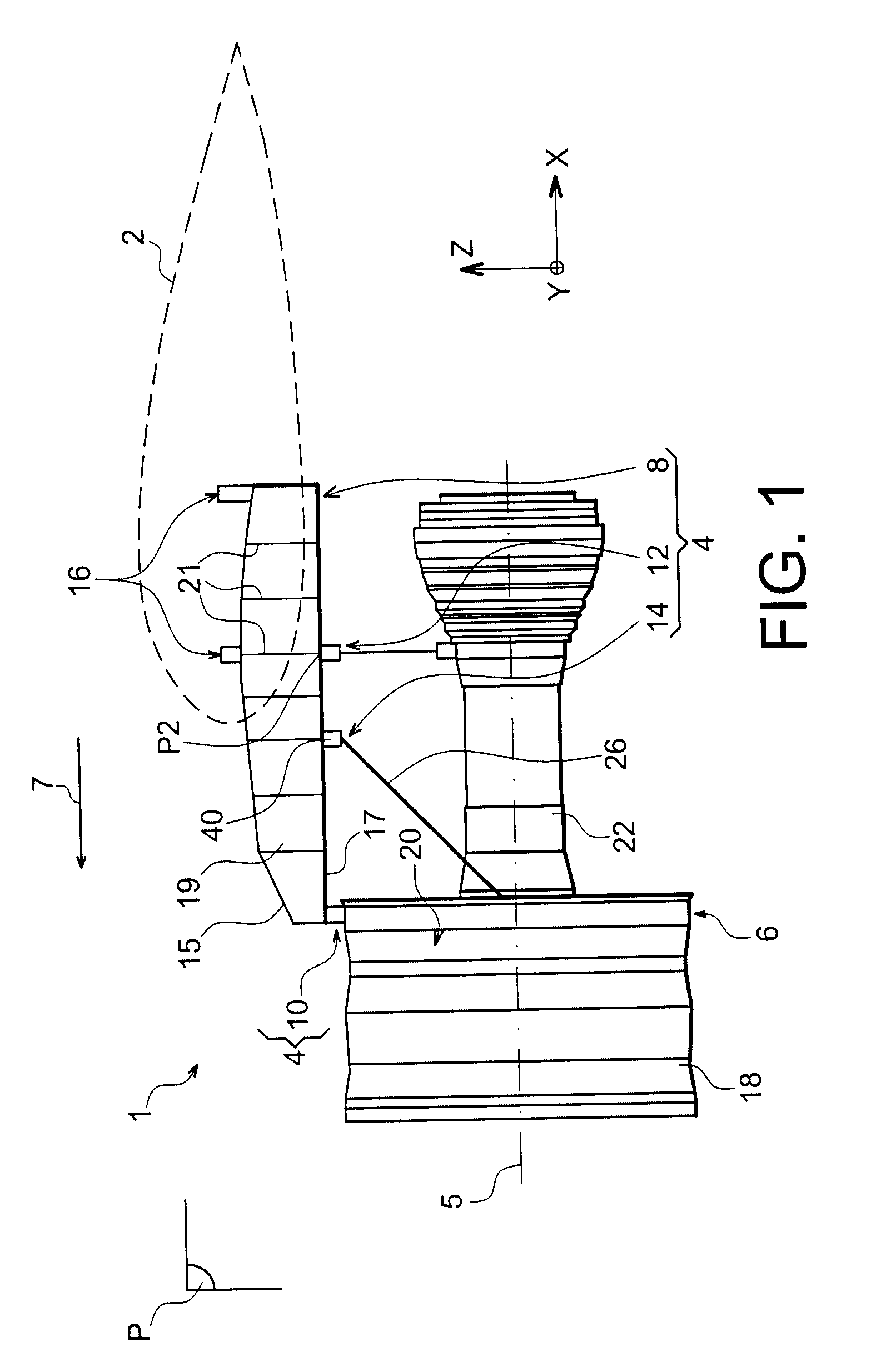
[0030]With reference to FIG. 1, an engine assembly 1 for an aircraft is seen, intended to be fixed under a wing 2 of this aircraft only illustrated schematically in dotted lines for sake of clarity, this assembly 1 including an attachment device 4 according to a preferred embodiment of the present invention, as well as an engine 6 such as a turbine engine, attached under this device 4.

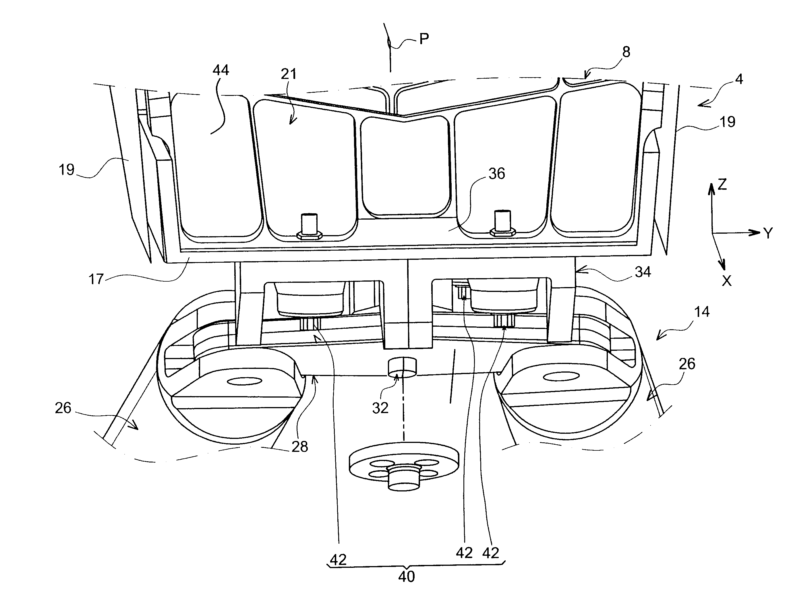
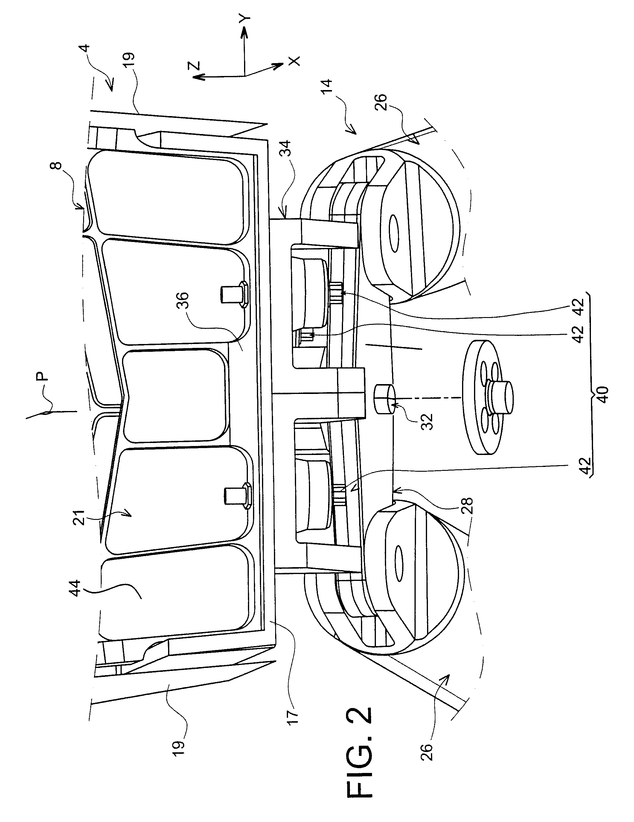
[0031]Globally, the attachment device 4 includes a rigid structure 8 bearing means for attaching the engine 6, these attachment means having a plurality of engine attachment members 10, 12, as well as a device for absorbing thrust-loads 14 generated by the engine 6.

[0032]Indicatively, it is noted that the assembly 1 is intended to be surrounded by a pod (not shown), and that the attachment device 4 includes another series of attachment members 16 with which the suspension of this assembly 1 may be provided under the wing 2 of the aircraft.

[0033]In the whole description which follows, by convention, the...


PUM


Abstract

A device for attaching an aircraft engine including a rigid structure forming a structure box, and a device for absorbing thrust loads including a main fitting fixedly mounted on one of the spars forming the structure box, by a fixing mechanism. The fixing mechanism includes a fixing peg mounted on the spar and including a main portion located on the outside relatively to the box, the fitting being crossed by the portion of the peg and pressed against the spar by a bell-shaped supporting washer surrounding the main portion and stressed by a screw crossing it, the latter being screwed into a barrel nut housed in a bore made within the main portion.

Description

TECHNICAL FIELD[0001]The present invention generally relates to a device for attaching an aircraft engine, for example intended to be interposed between an aircraft wing and the relevant engine, as well as to an engine assembly comprising such an attachment device.[0002]The invention may be used on any type of aircraft equipped with turbojet engines or turboprop engines.[0003]This type of mounting device also called an engine pylon suspension attachment or an <<Engine Mounting Structure >> (EMS), may indifferently be used for suspending an engine below the wing of the aircraft, mounting this engine above this same wing, or even for adding this engine to the rear portion of the fuselage of the aircraft.STATE OF THE PRIOR ART[0004]Such an attachment device is indeed usually provided for forming the connection interface between a turbine engine and a wing of the aircraft. It allows transmission of the forces generated by its associated turbine engine, to the structure of th...

Claims


Application Information

Patent Timeline
Patent Type & Authority Patents(United States)
IPC IPC(8): B64D27/26
CPCB64D27/26B64D2027/268B64D2027/264
Inventor BEAUFORT, JACQUES
Owner AIRBUS OPERATIONS (SAS)
Why Eureka
Try Eureka