
A display module, its assembly method and display device

A technology of a display module and an assembly method, which is applied to instruments, nonlinear optics, optics, etc., can solve the problems of poor adhesion of the edge-sealing tape, affecting the display effect of the display module, etc., and achieve the effect of improving the interference of the edge-sealing tape.

Active Publication Date: 2021-06-18
XIAMEN TIANMA MICRO ELECTRONICS
View PDF7 Cites 0 Cited by
  • Summary
  • Abstract
  • Description
  • Claims
  • Application Information

AI Technical Summary

Problems solved by technology

[0002] With the development of science and technology, liquid crystal displays are widely used in electronic terminals with display functions. Usually, the display module includes a display panel, a backlight module and an edge-banding tape. The edge-banding tape combines the display panel and the backlight module. As a whole, the traditional way of applying edge banding tape usually has joints at the corners of the display module, and there will be some related bad edge banding tapes at the joints of the edge banding tapes, which will affect the display module. The display effect of

Method used


Image

  • A display module, its assembly method and display device
  • A display module, its assembly method and display device
  • A display module, its assembly method and display device

Examples


Embodiment Construction

[0043] The following will clearly and completely describe the technical solutions in the embodiments of the present invention with reference to the accompanying drawings in the embodiments of the present invention. Obviously, the described embodiments are only some of the embodiments of the present invention, not all of them. Based on the embodiments of the present invention, all other embodiments obtained by persons of ordinary skill in the art without making creative efforts belong to the protection scope of the present invention.

[0044] In the following description, many specific details are set forth to facilitate a full understanding of the present invention, and thus the present invention is not limited by the specific embodiments disclosed below.

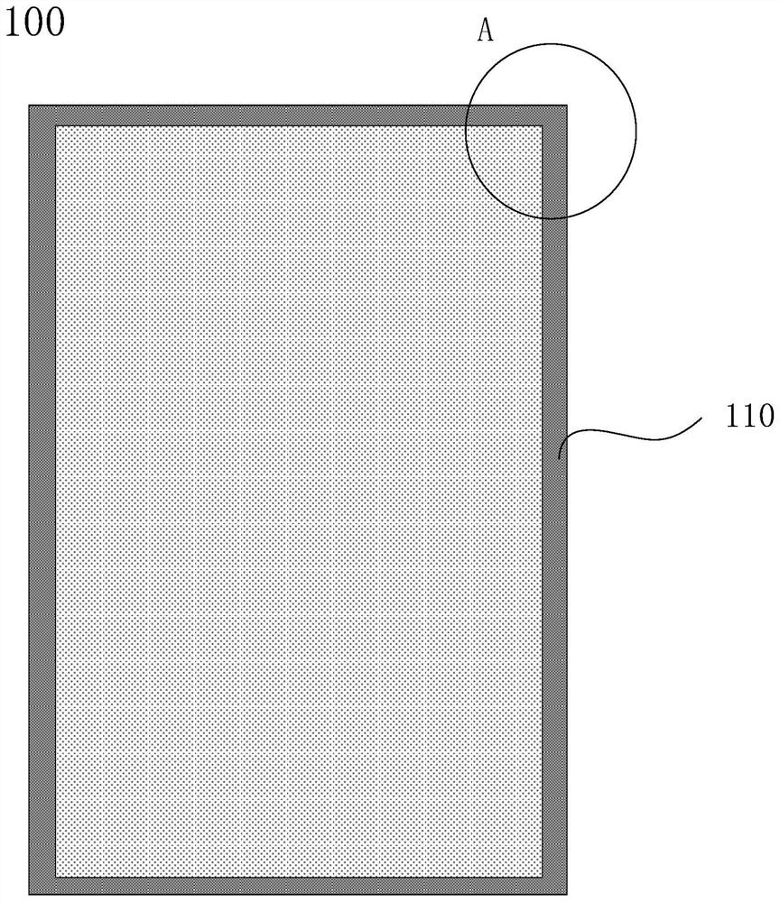
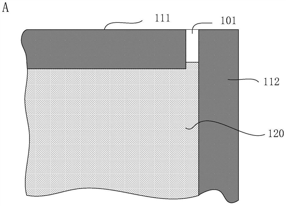
[0045] The inventor found in the course of research that, if figure 1 As shown in a top view of a display module, the display module 100 includes an edge banding tape 110; figure 2 for figure 1 The one shown shows an enl...


PUM


Abstract

The invention discloses a display module, an assembly method thereof and a display device. A display module includes: a backlight module, a display panel located on the light-emitting side of the backlight module, and an edge-sealing tape attached to the outer periphery of the backlight module and the outer periphery of the display panel; the edge-sealing tape includes a first The edge-sealing tape and the second edge-sealing tape, the first edge-sealing tape and the second edge-sealing tape at least partially overlap; the display panel includes a display substrate and an upper polarizer, and the upper polarizer is located on a side of the display substrate away from the backlight module; The edge-sealing tape attached to the outer periphery of the display panel does not overlap the upper polarizer, and the thickness of the edge-sealing tape in at least a part of the overlapping area of ​​the first edge-sealing tape and the second edge-sealing tape is less than or equal to the thickness of the upper polarizer . The invention also discloses an assembling method of the above-mentioned display module and a display device including the above-mentioned display module. The invention can improve the problem that the edge-sealing tape interferes when the display module is assembled with other components.

Description

technical field [0001] The invention relates to the field of display technology, in particular to a display module, an assembly method thereof, and a display device. Background technique [0002] With the development of science and technology, liquid crystal displays are widely used in electronic terminals with display functions. Usually, the display module includes a display panel, a backlight module and an edge-banding tape. The edge-banding tape combines the display panel and the backlight module. As a whole, the traditional way of applying edge banding tape usually has joints at the corners of the display module, and there will be some related bad edge banding tapes at the joints of the edge banding tapes, which will affect the display module. display effect. Contents of the invention [0003] In view of this, the present invention provides a display module, an assembly method thereof, and a display device to solve the above-mentioned problems in the prior art. [00...

Claims


Application Information

Patent Timeline
Patent Type & Authority Patents(China)
IPC IPC(8): G02F1/1339G02F1/1333
CPCG02F1/13338G02F1/1339
Inventor 刘远明
Owner XIAMEN TIANMA MICRO ELECTRONICS
Learn More