
Apparatus and method for driving sensorless motor

a sensorless motor and apparatus technology, applied in the field of electrical devices, can solve the problems of often failing to start-up of sensorless motors, and achieve the effect of increasing energy and effectively operating

Active Publication Date: 2012-05-29
INERGY TECH
View PDF7 Cites 33 Cited by
  • Summary
  • Abstract
  • Description
  • Claims
  • Application Information

AI Technical Summary

Benefits of technology

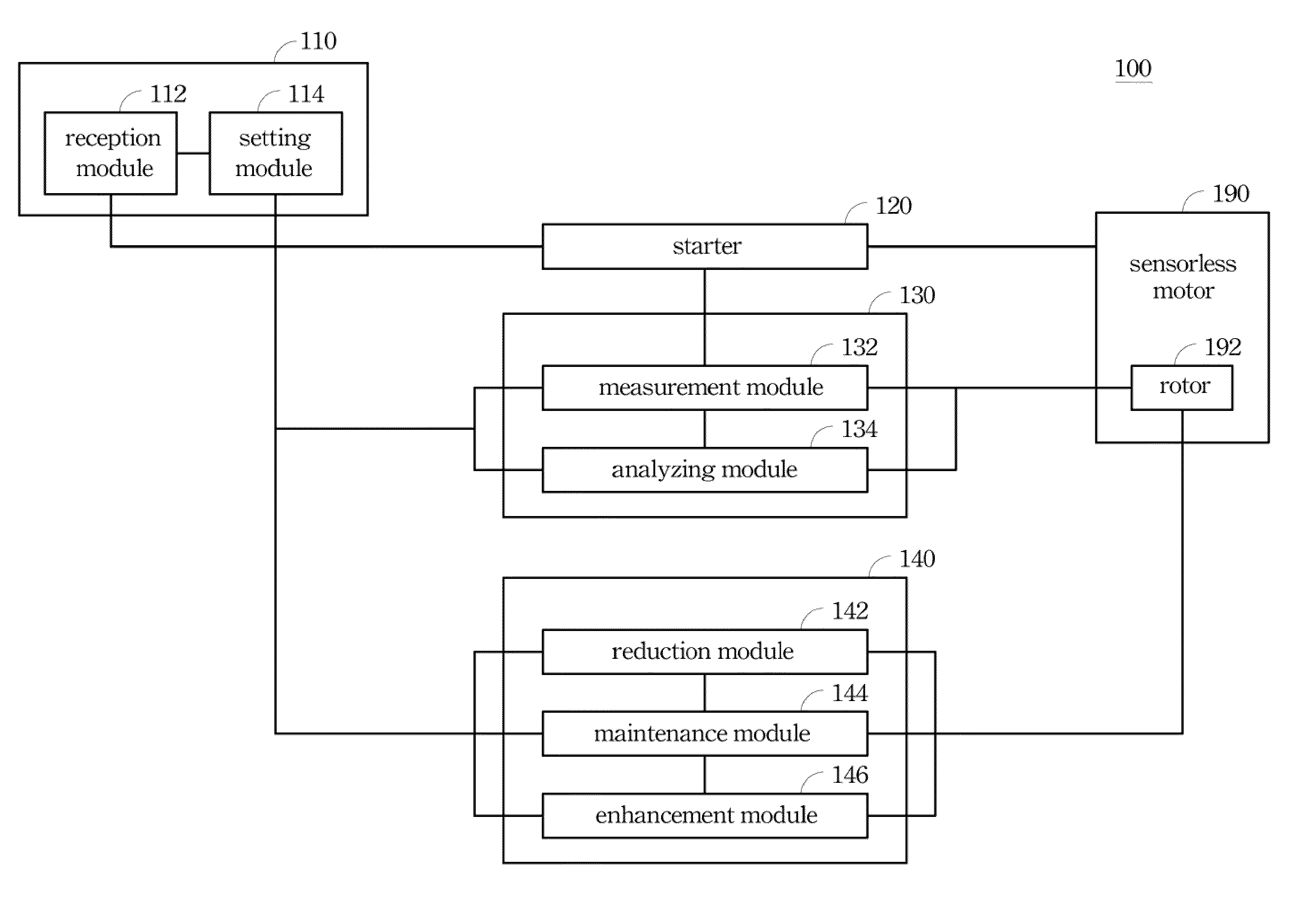
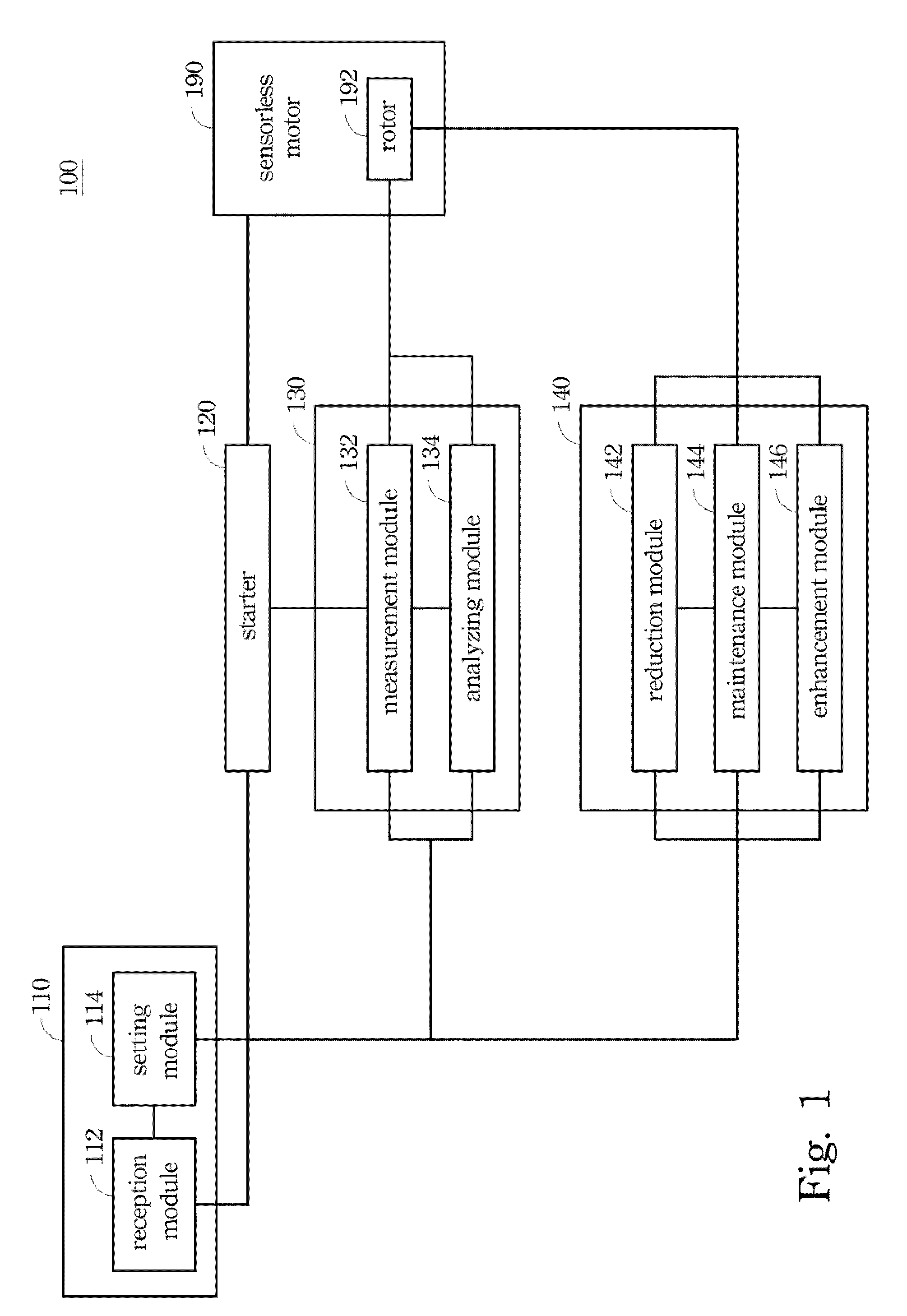
[0008]According to one embodiment of the present invention, the apparatus includes a receiver, a starter, a detector and an electrical controller. The receiver can acquire a control signal, wherein the control signal has information of a predetermined rotational speed. The starter can supply and progressively increase energy to the sensorless motor after the control signal is acquired, so as to rotate a rotor of the sensorless motor. The detector can detect a position of the rotor after the energy is supplied to the sensorless motor. The electrical controller can gradually regulate the energy after the position of the rotor is detected, so that the sensorless motor is maintained at the predetermined rotational speed.
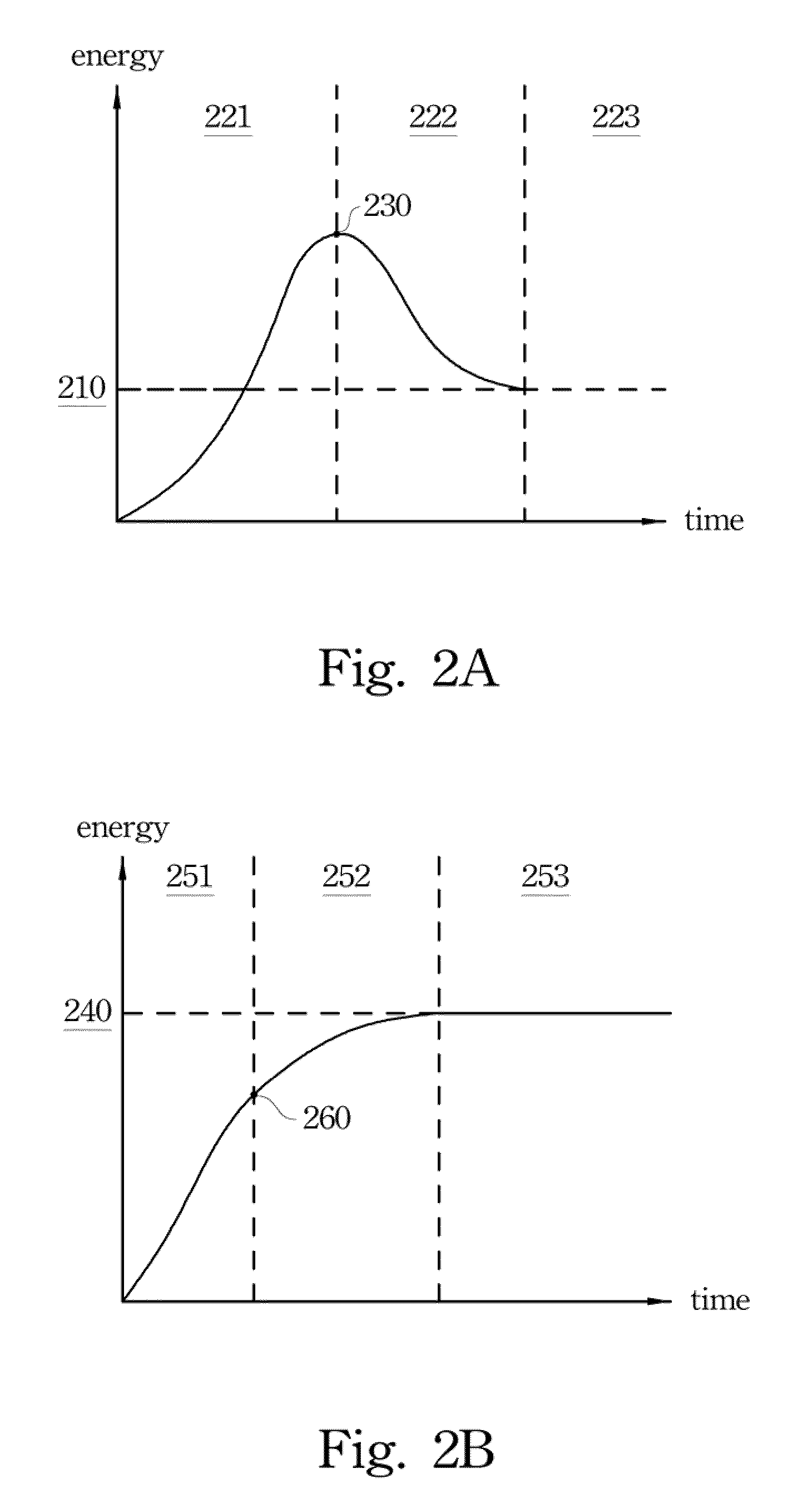
[0009]In this way, the apparatus smoothly supplies energy to the sensorless motor first, so as to prevent the failure in the start-up of the sensorless motor. Then, the position of the rotor is detected to signify that the sensorless motor is effectively operated, and furthermore the apparatus gradually regulates the rotational speed of the sensorless motor to conform to the predetermined rotational speed.
[0012]In this method, energy is smoothly supplied to the sensorless motor first, so as to prevent the failure in the start-up of the sensorless motor. Then, the position of the rotor is detected to signify that the sensorless motor is effectively operated, and furthermore the rotational speed of the sensorless motor is gradually regulated to conform to the predetermined rotational speed.

Problems solved by technology

In general, a conventional motor-driving circuit directly regulates the rotational speed of the sensorless motor to be constant whenever initially driving the sensorless motor, however, the sensorless motor often fails to start-up.

Method used


Image

  • Apparatus and method for driving sensorless motor
  • Apparatus and method for driving sensorless motor
  • Apparatus and method for driving sensorless motor

Examples


Embodiment Construction

[0019]In the following detailed description, for purposes of explanation, numerous specific details are set forth in order to provide a thorough understanding of the disclosed embodiments. It will be apparent, however, that one or more embodiments may be practiced without these specific details. In other instances, well-known structures and devices are schematically shown in order to simplify the drawing.

[0020]The terms used in this specification generally have their ordinary meanings in the art, within the context of the present disclosure, and in the specific context where each term is used. Certain terms that are used to describe the present disclosure are discussed below, or elsewhere in the specification, to provide additional guidance to the practitioner regarding the description of the present disclosure. The use of examples anywhere in this specification, including examples of any terms discussed herein, is illustrative only, and in no way limits the scope and meaning of the...


PUM


Abstract

An apparatus and a method for driving a sensorless motor are described and shown in the specification and drawings, where the method includes steps as follows. First, a control signal is acquired, where the control signal has information of a predetermined rotational speed. Next, energy is supplied and progressively increased to the sensorless motor, so as to rotate a rotor of the sensorless motor. Then, a position of the rotor is detected. Finally, the energy is gradually regulated so that the sensorless motor is maintained at the predetermined rotational speed.

Description

BACKGROUND[0001]1. Technical Field[0002]The present disclosure relates to an electronic device, and more particularly, an apparatus and a method for driving a sensorless motor.[0003]2. Description of Related Art[0004]With the fast development of the electronics industry, the application of sensorless motors has become more popular. In general, a conventional motor-driving circuit directly regulates the rotational speed of the sensorless motor to be constant whenever initially driving the sensorless motor, however, the sensorless motor often fails to start-up.[0005]In view of the foregoing, there is an urgent need in the related field to provide a novel apparatus capable of decreasing the failure rate of driving the sensorless motor. The present disclosure meets this need.SUMMARY[0006]The following presents a simplified summary of the disclosure in order to provide a basic understanding to the reader. This summary is not an extensive overview of the disclosure and it does not identif...

Claims


Application Information

Patent Timeline
Patent Type & Authority Patents(United States)
IPC IPC(8): H02P1/46
CPCH02P6/08H02P6/18H02P6/205H02P6/21
Inventor TSENG, CHIEN-CHUNGHSU, HSIEN-WENHSIEH, CHIEN-JEN
Owner INERGY TECH
Learn More