Antenna unit and mobile terminal therewith

a mobile terminal and antenna technology, applied in the field of antenna units, can solve the problems of poor user experience, inability to conduct communications, and difficulty in ensuring a predetermined communication distance, and achieve the effects of small antenna size, increased output, and small antenna

Inactive Publication Date: 2012-05-29
PANASONIC CORP
View PDF8 Cites 17 Cited by
  • Summary
  • Abstract
  • Description
  • Claims
  • Application Information

AI Technical Summary

Benefits of technology

[0010]According to the invention, the antenna unit of the size that can be installed in a mobile telephone can be provided and the antenna unit capable of ensuring the communication distance fitted to proximity communications can be provided. Further, the following problem occurring because the small size is realized can be solved: The coil of one turn is used for the need for increasing the Q value of the antenna to increase output of the antenna at the antenna transmitting time. However, the induced voltage of the antenna at the antenna receiving time lowers and it becomes impossible to obtain a reception signal. However, the resistance value of the reception circuit is adjusted with the impedance converter matching the impedance of the one-turn coil, so that the problem can be solved and the small antenna unit excellent in communication characteristic can be provided.

Problems solved by technology

To use a chip antenna, however, it becomes difficult to ensure a predetermined communication distance although there is a size merit.
If proximity communications are conducted using a mobile telephone at this distance, in fact, communications cannot be conducted because of the thickness of the cabinet of the mobile telephone or the like.
Even if an extremely thin cabinet is used, a mobile telephone and targets (reader / writer and tag) must be brought almost into contact with each other and the usability of the system is poor for the user.
However, the induced voltage of the antenna at the antenna receiving time lowers and it becomes impossible to obtain a reception signal.

Method used


Image

  • Antenna unit and mobile terminal therewith
  • Antenna unit and mobile terminal therewith
  • Antenna unit and mobile terminal therewith

Examples


embodiment 1

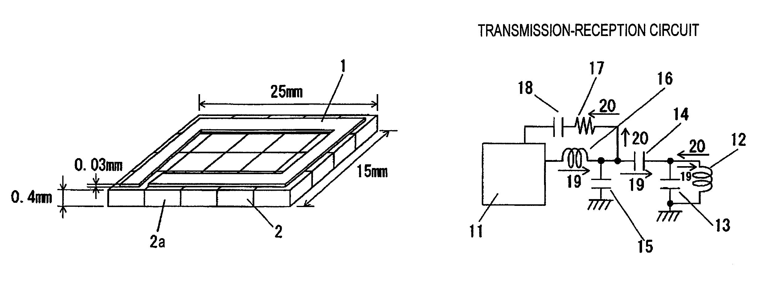
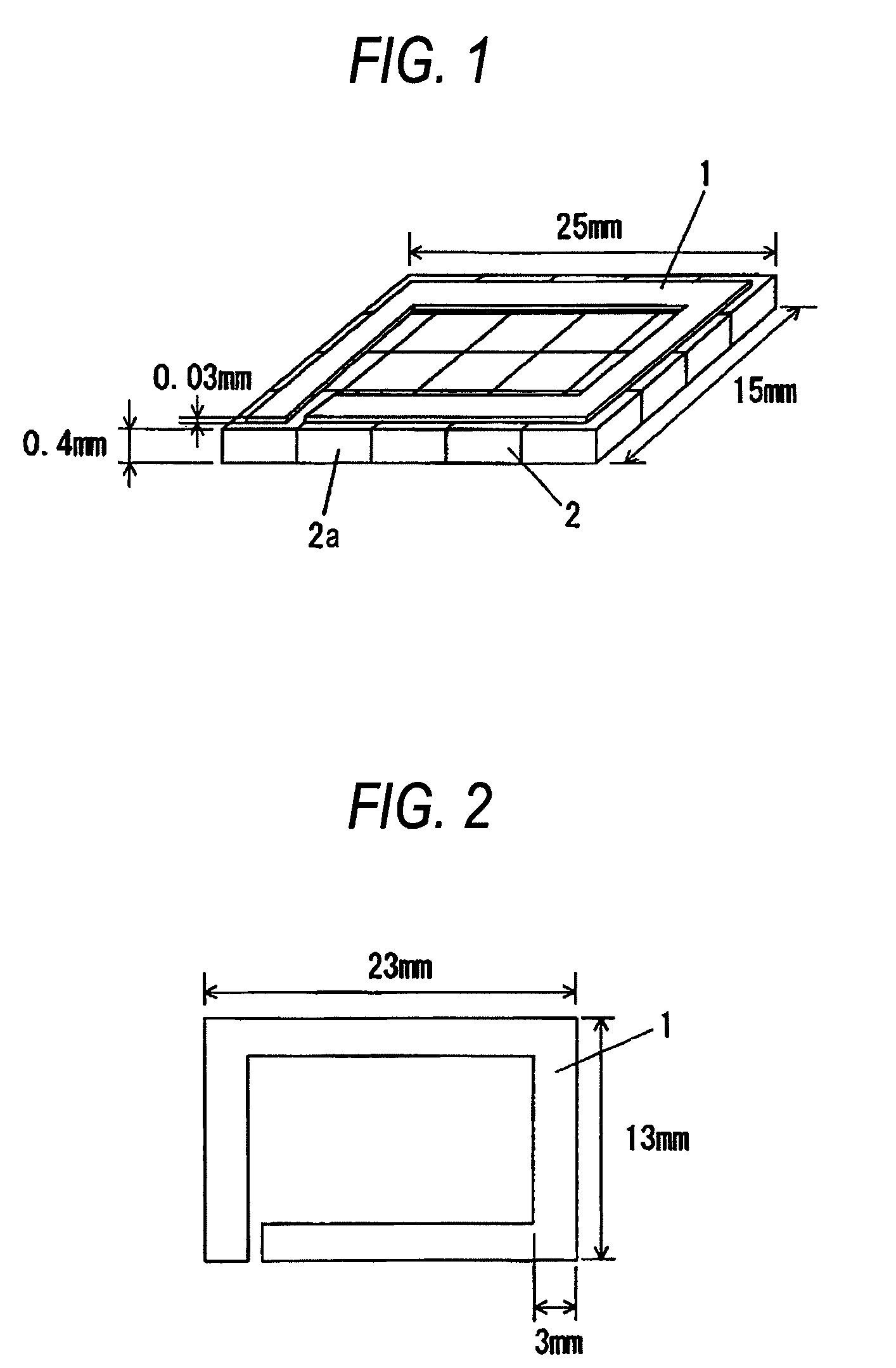
[0022]FIG. 1 is a configuration drawing to show an antenna unit in Embodiment 1 of the invention.

[0023]Numeral 1 denotes an antenna of a loop shape with one turn. Numeral 2 denotes a magnetic sheet provided below the antenna for decreasing the effect of metal on the periphery of the antenna; the magnetic sheet 2 is formed of a plurality of magnetic substances 2a each shaped like a fixed piece. In the embodiment, FIG. 1 shows the preferable size of three sides of the magnetic sheet 2 to miniaturize the antenna unit. This size is a size adapted for installation in a small communication device of a mobile telephone, etc. In the size, if an antenna of more than one turn is formed, a sufficient opening area of the antenna cannot be provided and it is difficult to provide the required communication distance. The sections making up the antenna unit will be discussed below in detail with FIG. 1:

[0024]To begin with, the antenna 1 will be discussed.

[0025]The antenna 1 is formed as a loop ante...

embodiment 2

[0066]Embodiment 2 of the invention will be discussed below with FIGS. 5 to 7. Detailed description is given invoking Embodiment 1.

[0067]FIG. 5 is a top view of an antenna unit in Embodiment 2 of the invention. In FIG. 5, an antenna 21 in a reader / writer mode and an antenna 22 in a tag mode are formed on the same plane and a magnetic sheet 23 is formed below the antennas 21 and 22.

[0068]The magnetic sheet 23 may be a resin layer if no metal body exists on the periphery of the antenna.

[0069]A switching circuit 24 is connected to the antennas 21 and 22 for switching terminals between the reader / writer mode and the tag mode. Numerals 25 and 28 denote terminals when the antenna unit is in the reader / writer mode and the terminals are connected to the antenna 21. Likewise, numerals 26 and 27 denote terminals when the antenna unit is in the tag mode and the terminals are connected to the antenna 22.

[0070]In the reader / writer mode, the antenna 21 of one turn is used, whereby the Q value of ...

embodiment 3

[0083]Embodiment 3 of the invention will be discussed below with FIGS. 8 and 9. Detailed description is given invoking Embodiments 1 and 2.

[0084]FIG. 8 is a configuration drawing to show an antenna unit in Embodiment 3 of the invention. As shown in FIG. 8 (a), an antenna unit 51 is of a stack structure; as shown in FIG. 8 (b), a reinforcement member 52, a resin sheet 53, an antenna 54, a resin sheet 55, a magnetic sheet 56, and a metal plate 57 are stacked in order from the top, and an opening is provided in the center.

[0085]The components will be discussed in detail.

[0086]First, the antenna 54 can use any material described above; in the embodiment, a copper plate is used.

[0087]Next, the magnetic sheet 56 can use any material described above; in the embodiment, ferrite is used and cell-shaped blocks 56a are combined to form the annular magnetic sheet 56.

[0088]Next, the resin sheet 55 will be discussed. As the resin sheet 55, for example, a resin represented by photo-setting resin, ...


PUM


Abstract

An antenna unit includes an antenna formed on a magnetic sheet. A transmission circuit includes an inductor, a matching capacitor, and the antenna connected in series, and a reception circuit includes the antenna, the matching capacitor, a resistor, and a capacitor connected in series. The antenna is formed as one turn, and the size of the antenna and the resistor involves a predetermined relationship.

Description

BACKGROUND[0001]1. Field of the Invention[0002]This invention relates to an antenna unit installed in a small communication device of a mobile telephone, etc., and in particular to an antenna unit adapted to a communication device of a mobile telephone, etc., having an NFC (Near Field Communication) function and a mobile terminal using the antenna unit.[0003]2. Description of the Related Art[0004]Hitherto, for example, an IC card system has been widely known as a system for conducting proximity communications. In the IC card system, a reader / writer generates an electromagnetic wave, thereby forming an RF field (magnetic field). When the IC card is brought close to the reader / writer, the IC card receives power supply according to electromagnetic induction and transfers data to and from the reader / writer.[0005]For example, NFC exists as a communication protocol for conducting proximity communications represented by the IC card system. In recent years, a mobile telephone has been cause...

Claims


Application Information

Patent Timeline
Patent Type & Authority Patents(United States)
IPC IPC(8): H01Q7/08
CPCH01Q1/38H01Q7/00
Inventor NAKAMURA, KOUICHINARUSE, TAKUMIFUKUSHIMA, FUMIOKIYOSUE, KUNIAKI
Owner PANASONIC CORP
Why Eureka
Try Eureka