RFID tag and method of manufacturing the same

a technology of rfid tags and manufacturing methods, applied in the field of rfid tags, can solve the problems of increased manufacturing cost of rfid tags and complicated manufacturing process, and achieve the effect of easy manufacturing and favorable communication characteristics

Inactive Publication Date: 2020-02-06
MURATA MFG CO LTD
View PDF0 Cites 1 Cited by
  • Summary
  • Abstract
  • Description
  • Claims
  • Application Information

AI Technical Summary

Benefits of technology

[0006]Therefore, the exemplary embodiments of the present invention are to provide an RFID tag having favorable communication characteristics as well as a structure that can be easily manufactured.
[0009]According to the exemplary embodiments of the present invention, the RFID tag having favorable communication characteristics and that has a structure that can be easily manufactured.

Problems solved by technology

However, in the case of the RFID tag described in Patent Document 1, the manufacturing process is complicated since it is necessary to vertically dispose a plurality of elongated metal posts closely on the substrate.
As a result, the manufacturing cost of the RFID tag is increased.

Method used


Image

  • RFID tag and method of manufacturing the same
  • RFID tag and method of manufacturing the same
  • RFID tag and method of manufacturing the same

Examples


first exemplary embodiment

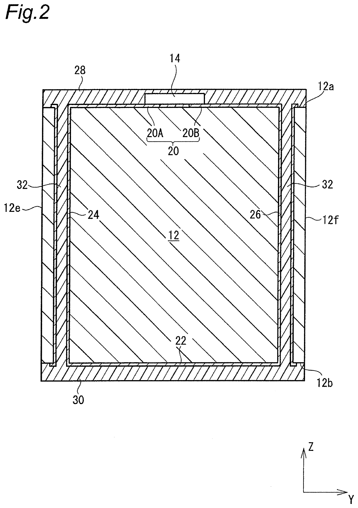
[0046]FIG. 1 is a perspective view showing a configuration of an RFID (RFID (i.e., “Radio-Frequency Identification”)) tag according to a first embodiment of the present invention, and FIG. 2 is a cross-sectional view of the RFID tag. An X-Y-Z coordinate system shown in the figures is for facilitating understanding of the invention, but it is noted that the exemplary coordinate system does not limit the invention.

[0047]As shown in FIG. 1, the RFID tag 10 has a rectangular parallelepiped substrate 12, and the substrate 12 is provided with an RFIC chip 14 and a coil conductor 16.

[0048]As described in detail below, the substrate 12 is produced by cutting a glass epoxy substrate having high heat resistance into multiple pieces, for example. The substrate 12 has a rectangular parallelepiped shape and includes a top surface 12a, a bottom surface 12b, and four side surfaces 12c, 12d, 12e, 12f. The top surface 12a and the bottom surface 12b are opposite surfaces in a Z-axis direction, the si...

second exemplary embodiment

[0077]An RFID tag of a second embodiment is different from the RFID tag 10 of the first embodiment in that a capacitor chip is included. Therefore, the second embodiment will be described mainly in terms of different points.

[0078]FIG. 4 is a perspective view showing a configuration of the RFID tag according to the second embodiment. It is noted that the same reference numerals are given to constituent elements that are substantially the same as the constituent elements of the first embodiment. The protective layers are not shown in the figure.

[0079]As shown in FIG. 4, an RFID tag 110 of the second embodiment includes a capacitor chip 140 mounted together with the RFIC chip 14 on the top surface 12a of the substrate 12. The RFIC chip 14 and the capacitor chip 140 are arranged parallel to a coil conductor 116. Thus, a resonance circuit is made up of the internal capacitance of the RFIC chip 14, the capacitance of the capacitor chip 140, the inductance of the coil conductor 116 (induct...

third exemplary embodiment

[0083]In the case of the second embodiment described above, as shown in FIG. 4, the coil conductor 116 is made up of one loop. In contrast, an RFID tag according to a third embodiment is made up of two loops. Therefore, the third embodiment will be described mainly in terms of different points.

[0084]FIG. 6 is a perspective view showing a configuration of the RFID tag according to the third embodiment. It is noted that the same reference numerals are given to constituent elements that are substantially the same as the constituent elements of the first embodiment. The protective layers are not shown in the figure.

[0085]As shown in FIG. 6, in an RFID tag 310 of the third embodiment, a coil conductor 316 is made up of two loops.

[0086]Specifically, a top-surface conductor pattern 320 on the top surface 12a of the substrate 12 is made up of three sub-conductor patterns 320A, 320B, 320C. A bottom-surface conductor pattern 322 on the bottom surface 12b of the substrate 12 is made up of two ...


PUM

PropertyMeasurementUnit
degree of freedomaaaaaaaaaa
surface areaaaaaaaaaaa
electromagnetic fieldaaaaaaaaaa

Abstract

An RFID tag is provided that has a rectangular parallelepiped substrate including a top surface, a bottom surface, and four side surfaces, an RFIC chip mounted on the top surface of the substrate, and a coil conductor connected to the RFIC chip. The coil conductor includes a conductor pattern disposed on the top surface, a conductor pattern disposed on the bottom surface, and a plurality of through-hole conductors penetrating the substrate and extending between the top and bottom surfaces. Moreover, a winding axis of the conductor pattern intersects with each of a pair of the side surfaces opposite to each other and having a largest area among the four side surfaces.

Description

CROSS REFERENCE TO RELATED APPLICATIONS[0001]The present application is a continuation of PCT / JP2018 / 015544 filed Apr. 13, 2018, which claims priority to Japanese Patent Application No. 2017-082269, filed Apr. 18, 2017, the entire contents of each of which are incorporated herein by reference.TECHNICAL FIELD[0002]The exemplary embodiments of the present invention relate to an RFID tag and a method of manufacturing the same.BACKGROUND[0003]In general, an RFID tag described in Patent Document 1 (identified below) is known as a small RFID (Radio-Frequency IDentification) tag that includes a coil conductor functioning as an antenna. The RFID tag described in Patent Document 1 has a plurality of metal posts that are portions of coil conductors disposed vertically on a substrate on which an RFIC chip is mounted in order to provide favorable communication characteristics.[0004]Patent Document 1: WO 2016 / 031408.[0005]However, in the case of the RFID tag described in Patent Document 1, the m...

Claims


Application Information

Patent Timeline
Patent Type & Authority Applications(United States)
IPC IPC(8): G06K19/077
CPCG06K19/07773G06K19/07722G06K19/07724
Inventor OMORI, RYOHEIKATO, NOBORU
Owner MURATA MFG CO LTD
Why Eureka
Try Eureka