Pressure controlling oscillator and communication device therwith

A technology of voltage-controlled oscillators and communication devices, applied to power oscillators, electrical components, etc., capable of solving problems such as performance degradation of voltage-controlled oscillators 50

Inactive Publication Date: 2002-05-29
MURATA MFG CO LTD
View PDF0 Cites 1 Cited by
  • Summary
  • Abstract
  • Description
  • Claims
  • Application Information

AI Technical Summary

Problems solved by technology

As a result, the performance of the VCO 50 deteriorates

Method used


Image

  • Pressure controlling oscillator and communication device therwith
  • Pressure controlling oscillator and communication device therwith
  • Pressure controlling oscillator and communication device therwith

Examples


Embodiment Construction

[0023] Next, preferred embodiments of the present invention will be described with reference to the accompanying drawings. In preferred embodiments of the present invention, the same or equivalent elements as those in conventional examples are designated by the same reference numerals, and repeated descriptions are omitted.

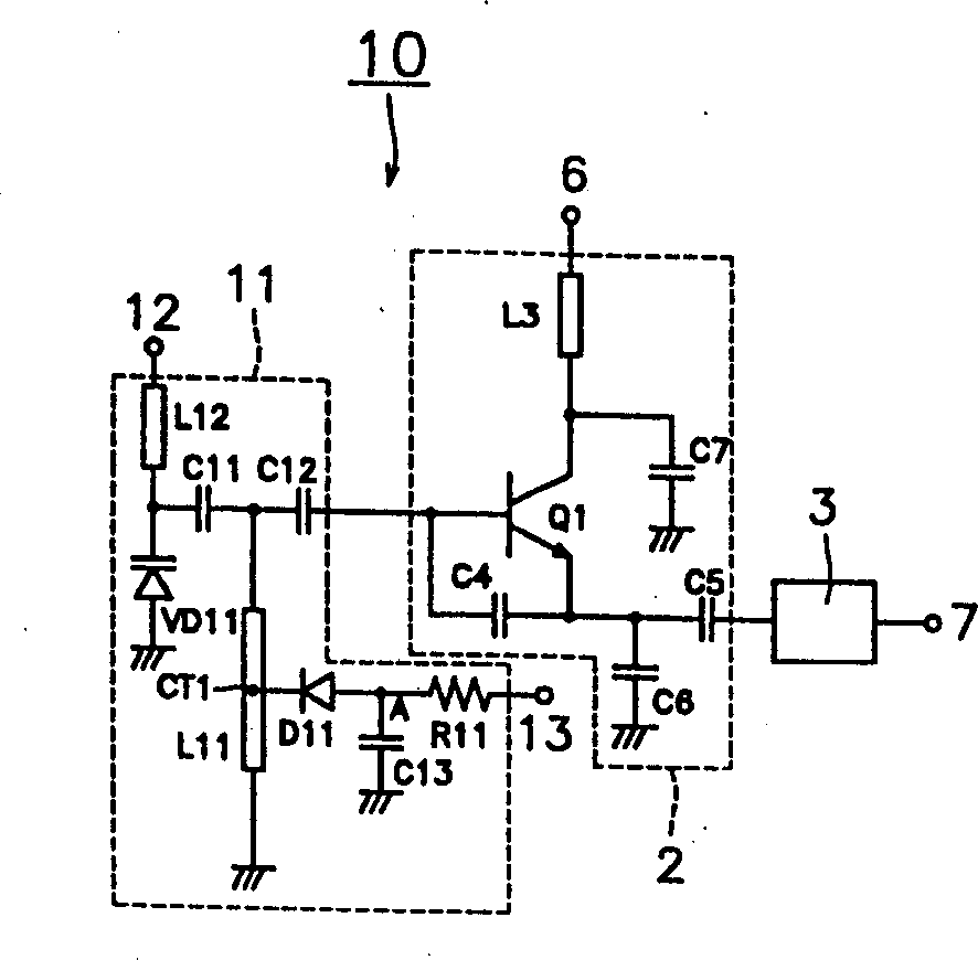
[0024] figure 1 is a circuit diagram of a voltage controlled oscillator according to the first preferred embodiment of the present invention;

[0025] The resonance circuit 11 selects one of two different frequencies, and outputs a signal that resonates at the selected frequency. The resonant circuit 11 includes a variable capacitance diode VD11, a diode D1 as a switching element, a strip line resonator L11, an inductor L12, a resistor R11, coupling capacitors C11 and C12, and a DC blocking capacitor C13.

[0026] The anode of the variable capacitance diode VD11 is grounded, and the cathode is connected to the power supply voltage terminal 12 through t...


PUM


Abstract

A voltage controlled oscillator changes two different frequencies to operate, and includes a resonance circuit, an oscillation circuit, and a buffer circuit. The resonance circuit includes a variable capacity diode, a diode which is a switching element, a strip line resonator, an inductor, a resistor, coupling capacitors, and a DC blocking capacitor. The intermediate tap CT1, which is located at a position other than the ends in the strip line resonator, of the strip line resonator is grounded via the diode as the switching element, and the DC blocking capacitor. The diode as the switching element is connected to a control terminal via the resistor.

Description

technical field [0001] The present invention relates to a voltage-controlled oscillator and a communication device comprising the same, in particular a voltage-controlled oscillator which switches a plurality of different frequencies during operation, and a communication device comprising such a voltage-controlled oscillator. Background technique [0002] In recent years, various communication systems using different frequencies have been widely used. To increase system utilization, it has become increasingly important that multiple communication systems can be accessed by a single communication device. In this case, a high-frequency oscillating circuit, such as a voltage-controlled oscillator constituting a local oscillating circuit of a communication device, needs to convert its frequency into a plurality of different frequencies in order to operate in many different communication systems. [0003] Figure 5 It is a circuit diagram of a conventional voltage-controlled osc...

Claims


Application Information

Patent Timeline
IPC IPC(8): H03B5/12H03B5/18
CPCH03B5/1847H03B5/18
Inventor 阿木裕史
Owner MURATA MFG CO LTD
Why Eureka
Try Eureka